
A simple grid control circuit
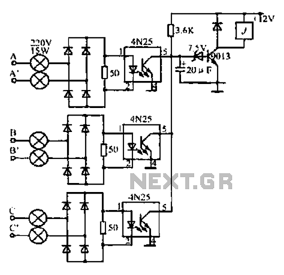
The described circuit is a complex arrangement designed for efficient power distribution in a split-phase system. The use of bulbs rated at 220V and 15W in the A-A indole path string indicates a focus on lighting efficiency and safety within the system. The four H-bridge configuration suggests that this circuit may be used for controlling motors or other inductive loads, allowing for bidirectional control and enhanced performance.
The detection circuit serves a critical role in monitoring the phase conditions of the power supply. By ensuring that the voltage, frequency, and phase sequence align with the grid, the system can maintain stability and prevent failures. The incorporation of capacitors suggests that power factor correction may be a consideration, enhancing the overall efficiency of the power system.
The mention of the Lanna Festival indicates that this setup is likely intended for temporary installations, highlighting the need for reliable performance under varying load conditions. The network control circuit operates at 12V, which is a common low-voltage standard for control systems, ensuring compatibility with various components and enhancing safety.
In automatic operation modes, the system can manage power distribution dynamically, adjusting to load changes without manual intervention. This is particularly important in applications where consistent performance is required despite fluctuations in demand. The rectification and regulation stages ensure that the control circuit receives a stable power supply, further enhancing reliability.
Overall, this circuit design emphasizes safety, efficiency, and adaptability, making it suitable for both permanent and temporary installations in large power distribution systems.A. B, C for big power split phase I, A + BC Rang generator phase line, A-A indole path string has a 2H220V/15W bulbs, bulbs recovery as both macro instructions J Sweet World as Well bucks electric brake sheet J. W Lamp wooden pole end that 4 H bridge consisting rely heap, B-B and c-c go the same way with the AA indole road situation b6 cap f Division. 3 mix with the same detection circuit f] or the composition of the circuit, H Ji wherein the phase detection circuit bright lights, JfW water action.
Only Bout given conditions F. That voltage generator, frequency, phase sequence, phase of the grid are the same. NIE all the lights go out, only action, driven AC contactor units. Well completion generators [make, pupa magnetic mussels should be good while Lanna festival turbine speed and generator voltage, frequency and the generator power just cotton division, in order to successfully liters net. Xu Jian network control circuit 12V power supply by the generator phase voltage after the transformer rectifier regulator to get down Hi, electric reasons drove off manually or automatically controlled, well IoJ fi power is turned off so well worthy of the net clamor circuit operation.
Related Circuits

The following circuit illustrates the Bedside Lamp Timer Circuit utilizing the CD4060 integrated circuit (IC). It operates for 30 minutes, with a blinking LED indicating the last 6 minutes of operation. The Bedside Lamp Timer Circuit is designed to provide...
The tuner is programmable via I²C-Bus and provides a FBAS signal at its output. There is also the homepage of Georg Acher containing information about this tuner. A control circuit has been developed for this tuner using the AT89C2051...
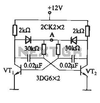
The circuit illustrated in Figure (A) consists of resistors R1 and R2 with values ranging from 15 to 18 kΩ, and capacitors C1 and C2 with capacitance values between 0.01 µF and 10 µF. Figure (B) depicts the oscillation...
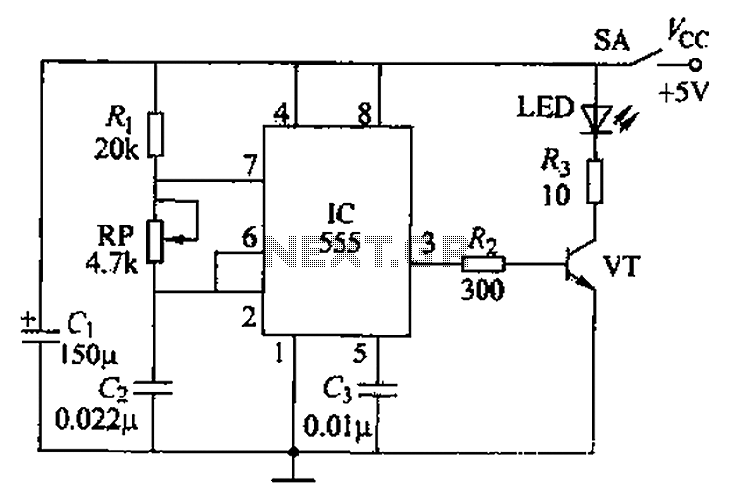
The circuit utilizes a 555 timer integrated circuit along with a transistor (VT) and several external components to create a multivibrator circuit. The charge and discharge time constants, Ti and T2, are defined, where Ti is approximately 0.7 times...
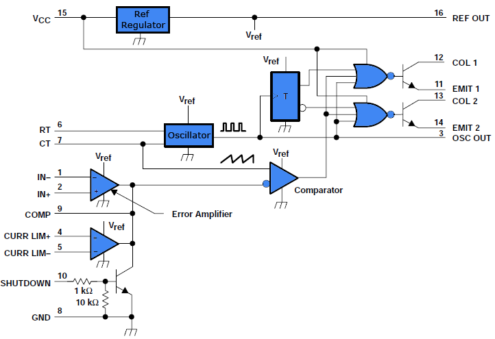
This document outlines a simple PWM (Pulse Width Modulation) DC to AC voltage inverter circuit based on the SG3524 integrated circuit. The SG3524 is a fixed frequency PWM voltage regulator control circuit that offers indifferent outputs suitable for both...
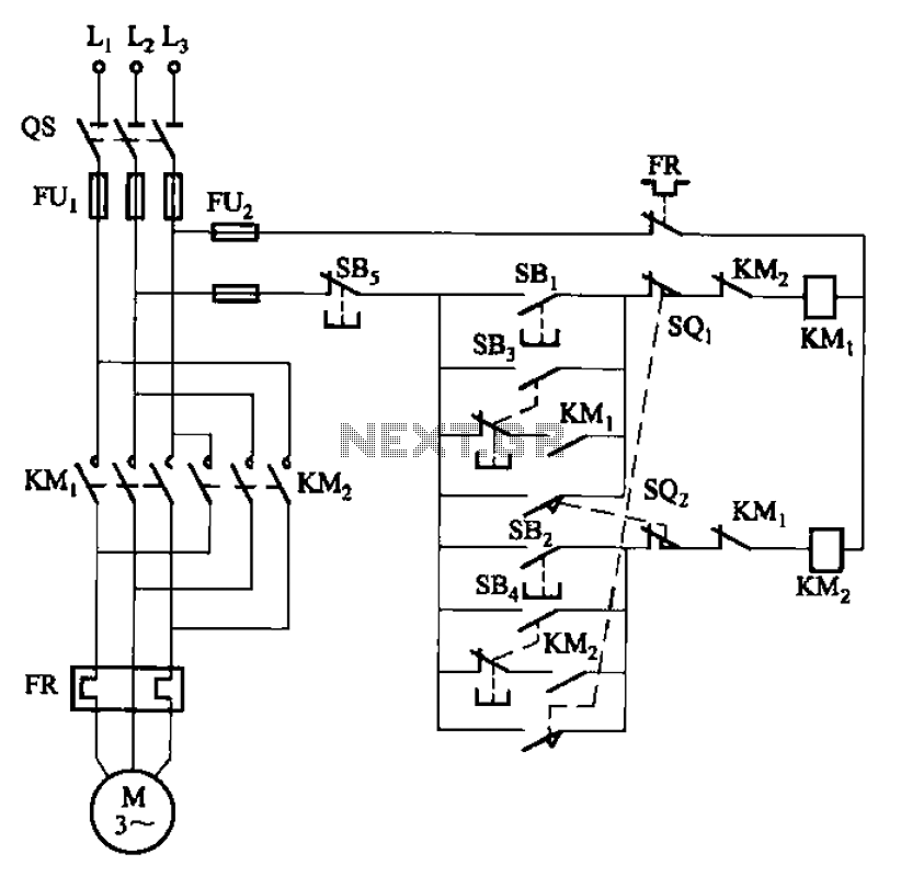
The circuit depicted in Figure 3-27 features a jog function that allows for precise adjustments of moving components. In the figure, SB3 and SB4 represent the forward jog and reverse jog buttons, respectively. When the SB3 button is pressed,...