
Improved multivibrator circuit
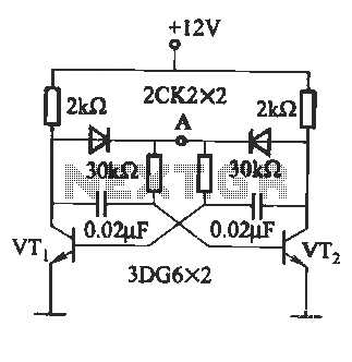
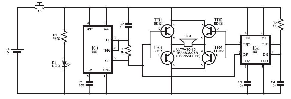
The described circuit appears to be a basic oscillator configuration, likely designed for generating high-frequency signals. The resistors R1 and R2, with their specified resistance values, form part of the timing components that determine the oscillation frequency. The capacitors C1 and C2 play a crucial role in setting the oscillation characteristics, where their capacitance values influence the charge and discharge cycles, ultimately affecting the frequency of oscillation.
In the context of oscillators, the range of 2 to 5 MHz indicates that this circuit is suitable for applications requiring high-speed signal generation. The adjustment of RP through a potentiometer allows for fine-tuning of the resistance, which can be critical for achieving the desired oscillation frequency. This feature enhances the versatility of the circuit, making it adaptable to various operational requirements.
The inclusion of diodes and transistors serves to stabilize the oscillator’s performance by preventing simultaneous saturation. This is important in maintaining the integrity of the oscillation and avoiding distortion in the output signal. Diodes can be used for clamping and protecting the circuit from voltage spikes, while transistors can serve as amplifiers or switches within the oscillator circuit, ensuring reliable operation.
Overall, this circuit design is indicative of a fundamental oscillator application, with components carefully selected to achieve specific operational parameters. The combination of resistors, capacitors, and active components like diodes and transistors allows for a robust design capable of generating stable high-frequency oscillations.Circuit shown (A): R], R2 is 15 ~ 18kn, Cl, C2 is 0.01 ~ 10 "F. Figure (b): oscillation frequency, up to 2 ~ 5MHz, RP is adjusted by potentiometer FIG. (C) access. diodes, transistors can be prevented by two simultaneous saturation stop vibration.
Related Circuits
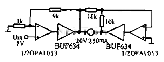
A bridge motor drive circuit is illustrated, featuring a driving stage composed of four transistors. The control circuit includes four terminals labeled A, B, C, and D, which facilitate the control of forward or reverse motor rotation. The control...
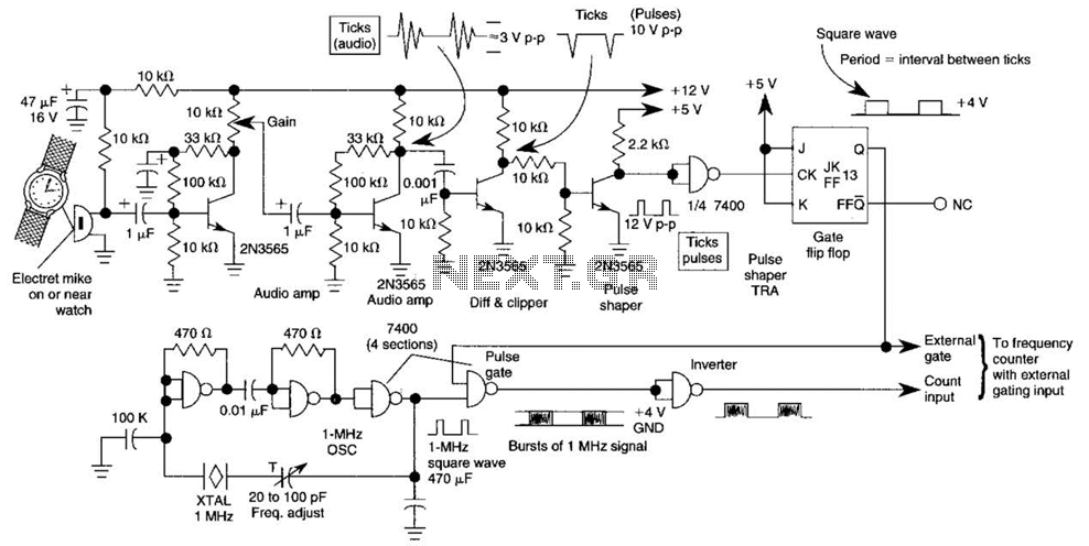
This circuit adapts a frequency counter to measure intervals. It was originally utilized as a shutter speed checker for photographic applications. The watch ticks are clipped, shaped, and formed into a square wave. This square wave is employed to...
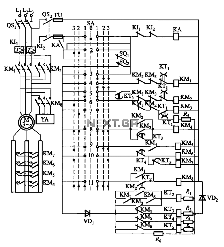
The system involves a master controller and a PQS1 Series Magnetic control panel, which includes a control circuit designed to manage the bridge crane hoist lifting mechanism. The master controller handle SA features seven positions: alongside the zero position,...

This smoke detector electronic project is designed using the LM1801 and common electronic components. The smoke detector circuit diagram does not utilize ionization detection, gas sensors, or optocouplers; instead, it employs two photoresistors (LDRs) and an LED. The circuit...

The circuit depicted in Figure 3-84 allows two electric motors to be started independently. The motors can only be activated after pressing the main stop button (SBz) to release contact KMi. Following this, the auxiliary stop button (SB4) can...
This ultrasonic sensor circuit consists of a set of ultrasonic receivers and transmitters that operate at the same frequency. When an object moves within the covered area, the circuit's balance is disturbed, triggering the alarm. The ultrasonic circuit is...
Warning: include(partials/cookie-banner.php): Failed to open stream: Permission denied in /var/www/html/nextgr/view-circuit.php on line 713
Warning: include(): Failed opening 'partials/cookie-banner.php' for inclusion (include_path='.:/usr/share/php') in /var/www/html/nextgr/view-circuit.php on line 713