
Seven blinker circuits
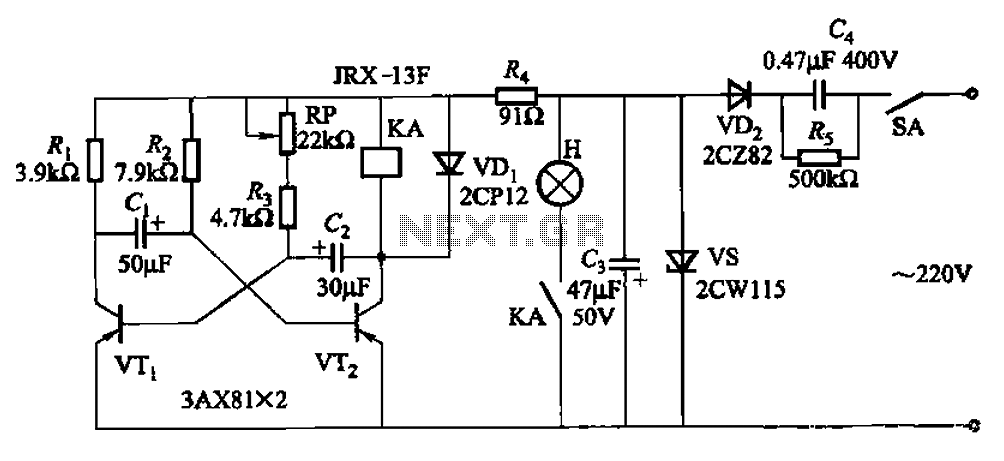
The described multivibrator circuit utilizes two transistors (VTi and VTZ) configured to create an astable multivibrator, which generates a continuous square wave output. This configuration is commonly employed in applications such as flashing lights or tone generation. The operation of the circuit hinges on the charging and discharging cycles of the capacitors within the RC networks, which dictate the frequency of oscillation.
The adjustment potentiometer RP plays a crucial role in fine-tuning the timing characteristics of the circuit. By varying its resistance, the time intervals for which the lights are turned on (high state) and off (low state) can be adjusted. This allows for customization of the light blinking rate, enhancing the versatility of the multivibrator in different applications.
The RC networks connected to each transistor help establish the necessary time constants for the oscillation. The resistors and capacitors can be selected based on the desired frequency range, with the time period of the output signal being determined by the formula T = 0.693 * (R1 + R2) * C, where R1 and R2 are the resistances in the RC networks and C is the capacitance. The output from the multivibrator can be connected to various load devices, such as LEDs or other light sources, to create visual indicators or alerts.
Overall, this self-excited multivibrator circuit exemplifies a straightforward yet effective design for generating timed signals, suitable for a variety of electronic applications. By the transistor VTi, VTZ composition self-excited multivibrator. Adjustment potentiometer RP and two RC transistors related parameters, time to change the lights and the ligh ts out time.
Related Circuits
If the audio input is a microphone, it is expected to precede an amplifier to achieve an output power of approximately 8W. The amateur seeking to enhance a small transmitter, which is likely already constructed, can utilize this circuit,...
This circuit consists of three single-junction transistor time relay circuits utilizing a pulse charging mechanism, allowing for extended delay times of up to several minutes. The first stage delay circuit incorporates unijunction transistors (VTi) and other components, where capacitor...
A 1200 Watt lamp dimmer circuit is designed to control lighting levels and is capable of managing up to 1200 Watts. This circuit utilizes the Q4015LT, which combines a Diac and a Triac for 230V dimming applications. It serves...
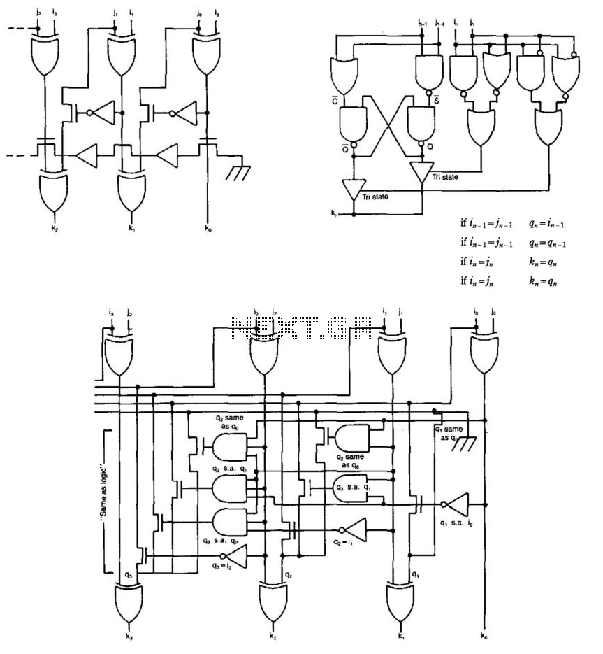
Some circuits that add binary numbers experience time delays due to carry propagation. This issue has been partially addressed by the carry look-ahead adder. However, the complexity of this method typically limits its application to no more than 4...
This is a car alarm simulator that uses an LED as a simulation output. This simple circuit can indicate whether a car is running or not by detecting the voltage difference when the car is on or off. This...
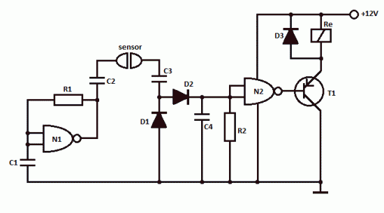
This simple water detector circuit utilizes alternating voltage to prevent electrode corrosion. It is easy to construct and employs N1 as a trigger Schmitt gate to generate the AC signal. When a conductive substance, such as an aqueous solution,...
Warning: include(partials/cookie-banner.php): Failed to open stream: Permission denied in /var/www/html/nextgr/view-circuit.php on line 713
Warning: include(): Failed opening 'partials/cookie-banner.php' for inclusion (include_path='.:/usr/share/php') in /var/www/html/nextgr/view-circuit.php on line 713