
antenna tuner circuits
The Johnson 275 watt and Kilowatt Matchboxes are designed as RF tuners that facilitate impedance matching between the transmitter and the antenna. These devices employ a fixed coupling link, which presents a limitation in flexibility compared to tuners utilizing adjustable coupling mechanisms. The tuners operate as balanced voltage sources, which can be less efficient than current sources, particularly in certain applications where current-driven systems may provide superior performance.
The central component of the Johnson Matchbox is the dual-differential matching capacitor, C2, which consists of four capacitor sections. This design allows for fine-tuning of the matching process but introduces complexity that may not be necessary for all users. The two grounded sections of C2, while not detrimental to performance, add unnecessary complexity and cost. The performance of the tuner remains effectively unchanged whether these sections are included or omitted, indicating that their presence may be more a matter of design choice than functional necessity.
In contrast, the Ameritron ATR-10 antenna tuner offers a simpler design with a tapped inductor and an output balun, allowing for a more straightforward approach to impedance matching. This design choice reflects a different philosophy in tuner construction, prioritizing ease of use and potentially lower production costs.
Both the Johnson Matchbox and the Ameritron ATR-10 utilize resonant circuit principles to achieve impedance matching. The tuners can be configured to operate in either series or parallel resonance modes, depending on the capacitor settings. The interaction between the capacitors and the inductor determines the impedance characteristics of the output circuit, with the positioning of tap points influencing the maximum impedance ratios achievable.
In summary, while both tuners serve the same fundamental purpose, their design philosophies differ significantly. The Johnson Matchbox, with its more complex capacitor arrangement, provides a versatile but potentially over-engineered solution, whereas the Ameritron ATR-10 emphasizes simplicity and ease of use, making it a compelling alternative for users seeking effective impedance matching without the intricacies of the Johnson design.The Johnson 275 watt and Kilowatt Matchboxes are both unnecessarily exaggerated and unnecessarily maligned. They are not exceptional tuners, and are not poor designs. The primary drawbacks are the fixed coupling link, and the fact they are balanced VOLTAGE sources, not the generally more ideal current source.
C2 is special and expensive. C2 is a d ual-differential MATCHING capacitor with four capacitor sections. C2 has two insulated rotor areas in differential tied to the balanced outputs, two independent stators, and two commonly-connected stators. C2 is overcomplicated, with unnecessary sections in C2. The unnecessary sections of C2 are the two sections connected to ground. The two unnecessary grounded sections neither benefit nor harm tuner performance significantly. The tuner works almost identically when grounded inner sections of MATCHING capacitor C2 are eliminated.
The fact Johnson included unnecessary grounded sections of C2 does not make it a bad tuner. The inclusion of unnecessary (basically harmless) sections only means Johnson wasted money and space inside the tuner by including the nearly-useless grounded C2 MATCHING capacitor sections. In the 1980`s, I designed an Ameritron ATR-10 antenna tuner (not related to any current Ameritron products).
The ATR10 Ameritron was a companion to the AL84, and was designed as a companion bandpass 600-watt antenna tuner. The Ameritron ATR10 antenna tuner used a network functionally identical to the Johnson Matchbox series.
The ATR-10 was a single-ended tuner with an output balun. The ATR-10 used a tapped inductor instead of a coupling link. The basic simplified ATR10 antenna tuner matching circuit is shown below: Tap A is from a standard rotary switch contact. This tap always leads tap B toward the hot end of the tank. The amount of lead controls tank Q. Tank Q determines matching range and power rating, just as changing turns controls Q and range in any link coupled tuner.
Tap B is the band selector tap. This switch is a progressively-shorting (pick-up-and-hold) contact. Tap B determines inductance, which in turn sets frequency range. If we ignore the nearly useless grounded sections of C2 in the Johnson Matchbox, and understand a link is not much different electrically from the tap on the ATR10 Ameritron, we see the ATR10 and EFJ Matchbox are electrically identical in matching function. The Ameritron ATR10 and E. F. Johnson Matchbox tuners both use a combination series and parallel resonant output circuit. This circuit actually forms a T network. If we assume C2 is set to resonance and C1 has zero capacitance, we have a classic link coupled series tuned network with low output impedance.
If C2 is set to a high capacitance value, and C1 is tuned to resonance, we have a classic parallel tuned network. In both cases the tap-point A distance above band-point B sets maximum impedance ratio, because the tap point determines maximum operating Q and available voltage at the common junction of L1 top, C1, and C2.
C1 primarily determines load resistance value, while C2 primarily compensates reactance. Ironically, Johnson calls C2 Match and C1 Tune! Lowest impedance is with C1 open and C2 tuned to correct resonance. Impedance increases as C1 is moved closed, with C2 progressively closed. Highest impedance is with C2 fully closed and C1 tuned to resonance. If we are mindful of how the ATR10 works, we will also understand the more complex Johnson Matchbox. In the case of the Matchbox series, the number of turns on the LINK coil sets matching range and maximum power capability of the tuner. With fewer turns on the E. F. Johnson tuner link compared to turns on L2, the system has higher voltages and wider matching range. This reduces power rating, but increases match range and selectivity. With more turns on the E. F. Johnson`s link compared to turns on L2, the system has lower voltages and wider matching range. This increases pow 🔗 External reference
Related Circuits
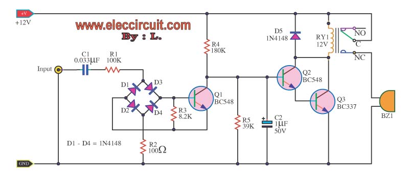
The telephone repeater is a circuit designed to amplify the call signal, making it louder than the original. This circuit has been developed in response to specific requests. The telephone repeater circuit functions by receiving the incoming audio signal from...
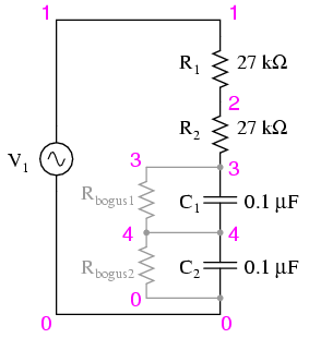
Construct the circuit and measure the voltage drops across each component using an AC voltmeter. Additionally, measure the total (supply) voltage with the same voltmeter. It will be observed that the individual voltage drops do not sum up to...
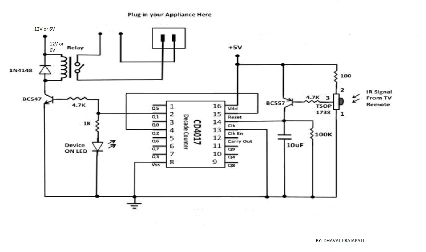
The circuit utilizes a 4-bit encoder to generate data, which is then modulated using an RF modulator for transmission. On the receiving end, the signal is demodulated, and a decoder retrieves the 4-bit data. The pin configuration for the...
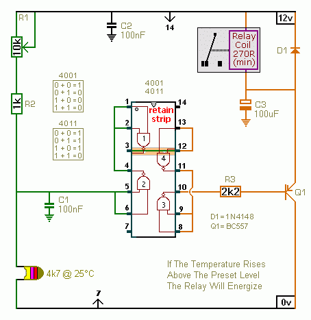
A CMOS 4001 or a CMOS 4011 can be utilized in this circuit, as both contain four two-input gates. The inputs of each gate are connected together, allowing them to function as simple inverters. This means that when both...
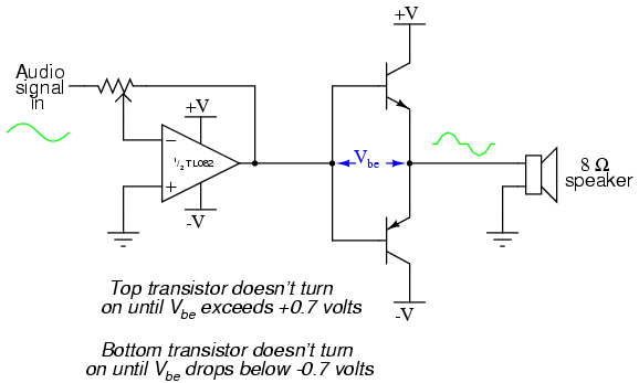
This project is an audio amplifier designed to amplify output signals from small radios, tape players, CD players, or other audio signal sources. For stereo operation, two identical amplifiers must be constructed—one for the left channel and another for...
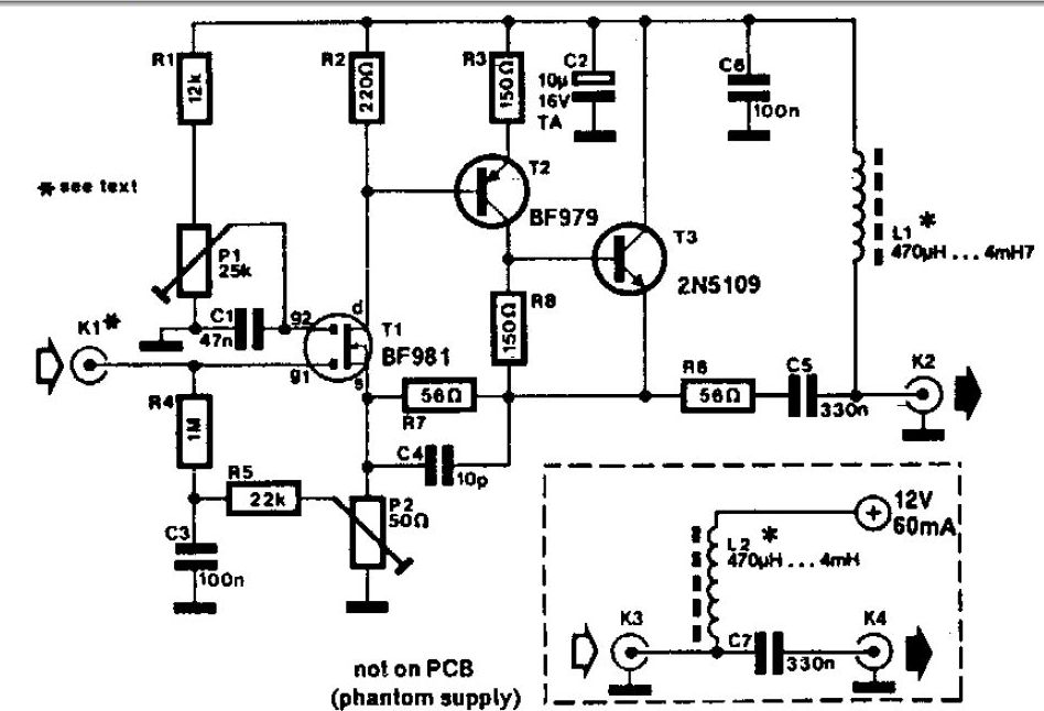
A whip antenna measuring between 30 to 50 cm is capable of receiving signals from 10 MHz to over 220 MHz. The circuit incorporates a BF981 dual-gate MOSFET (T1), which offers low noise characteristics, high input impedance, and enhanced performance. The...
Warning: include(partials/cookie-banner.php): Failed to open stream: Permission denied in /var/www/html/nextgr/view-circuit.php on line 713
Warning: include(): Failed opening 'partials/cookie-banner.php' for inclusion (include_path='.:/usr/share/php') in /var/www/html/nextgr/view-circuit.php on line 713