
tune coil
The circuit described integrates a tuning coil system designed to optimize spark length in a transformer coil configuration. The system employs a 12V DC motor to actuate a movable tap on the tuning coil, which can adjust the inductance in real-time. The tuning coil's inductance can be varied from 0 to 20 µH, allowing for fine-tuning of spark length across different transformer sizes.
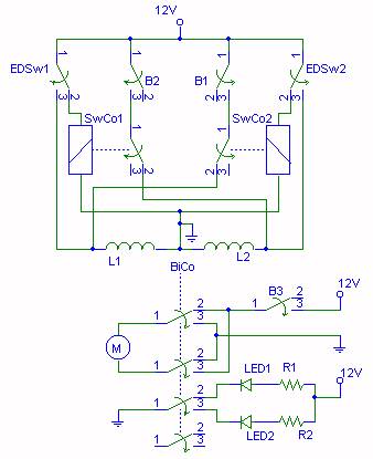
The mechanical arrangement includes a motor connected to a gearbox for torque amplification, facilitating the movement of the tap. The tap's position is monitored using two end detection micro switches (EDSw1 and EDSw2), which are isolated from the high-voltage primary circuit to ensure operator safety. The levers attached to these switches are designed to provide reliable actuation while minimizing friction, possibly augmented by springs to ensure effective contact with the switches.
A bistable contactor (BiCo) is employed to control the motor's direction based on inputs from the micro switches. However, to prevent simultaneous activation of both coils of the bistable contactor, which could lead to motor stalling or damage, additional contactors (SwCo1 and SwCo2) are introduced. These contactors serve as safety interlocks, ensuring that once one end switch is activated, the corresponding preselection button cannot be engaged until the motor is reset to a neutral position.
User interface controls include three buttons: one for motor activation (B3) and two for direction selection (B1 and B2). Each of the direction buttons is equipped with an LED indicator (LED1 and LED2) to provide visual feedback regarding the current operational state of the system. This design ensures that the operator is informed of the system's status, reducing the likelihood of operational errors.
In summary, this circuit design emphasizes safety, efficiency, and ease of use, enabling real-time tuning of transformer coils while minimizing the risk of damage through careful mechanical and electrical interlocking strategies.And normally tuning is not easy: you`ll fire the system up and try to notice the spark length, shut it off (and pull the plug!), re-tune (move the tap on the primary), fire it up again and try to remember the spark length of the run before, and do it all over and over again and again until the spark length is maximized. But things canbe much easie r: by using a tuning coil, tuning can be done on-the-fly: online - while the system is sparking. You immediately can see if more or less turns will be optimum for the spark length. My tuning coil will give me something 0-20uH additional inductance. So I can tune (+/-20% from optimum value) my 2"-TC with 3 turns, my 4"-TC with 4 turns and the BlueThunder (10"-TC) with the full 21 turns. I`ll use a 12VDC motor (with gear box) to turn the moving tap (consisting of 6 spring loaded contacts) of the tuning coil.
Up to now I tested it with 12V, amperage is only up to 200mA. Detecting the end positions will be a bit tricky. I`ll try to mount two levers which will be moved by the tap or better by the guided "block" at the axis so that the point of maximum inductance available can be adjusted. This levers will activate micro switches(EDSw1 and EDSw2) - of course well isolated from the voltage in the primary circuit.
The isolated lever will have some mass and friction, so I perhaps have to load itby an additional spring to help thespring in the micro switch. The micro switches (EDSw1 and EDSw2) are intended to activate a bistable contactor (BiCo) which will change the direction of rotation.
However the switches will activate the bistable contactor (BCo) not directly. There is a good reason to add an additional contactor (SwCo1 and SwCo2) for each end detection micro switch (EDSw1 and EDSw2). This is because of the way the tuning coil is operated. I plan to use three buttons here. One (B3) is to activate the motor which is only running while the button is pressed. With the other two buttons (B1 and B2) the direction of rotation can be preselected -each button (B1 and B2) will get its own indicator LED (LED1 and LED2) to show the current state of the bistable contactor (BiCo).
One problem could arise: if the tuning coil is running into one of the end detection switches (EDSw1 and EDSw2) so that the switch is pressed, the belonging coil (L1 or L2) of the bistable contactor (BiCo) is activated. If this is not noticed by the operater and he will press the button for theother direction, both coils of the bistable contactor would be activated and the motor will not stop or even change direction so that the tuning coil could be damaged.
Not good. Therefore, the two preselection buttons (B1 and B2) will be locked (= turned off = deactivated) by the two contactors SwCo1 and SwCo2 mentioned before. The two contactors SwCo1 and SwCo2 can be omitted if I can install end detection switches with can switch two independent citcuits (1x closing + 1x opening)
🔗 External reference
Related Circuits

Due to limited space, a small 6V battery is utilized, and the voltage is reduced by 1.2V to 4.8V using diodes D1 and D2. The PicAxe chip is employed in the circuit. In this circuit design, the primary power source...

A field effect transistor amplifier features a fixed bias input source with feedback, resulting in very high input impedance and low capacitance. It drives a field effect transistor or emitter follower, despite having a very low output impedance, utilizing...
This circuit is designed to demonstrate high-frequency high voltage, capable of producing voltages up to approximately 30 kV, depending on the transformer used. It is economical and straightforward to construct, primarily utilizing a standard TV flyback transformer. The circuit...

The coil has been enhanced with additional turns, necessitating an improvement in insulation. Epoxy was chosen as the insulating material, with an increased quantity applied over the soldered connections. To ensure the reliability and performance of the coil, the additional...
The thyristor-fired coilgun is a prevalent variant, primarily due to its high voltage and pulsed current capabilities. A diagram of the system designed for these experiments is presented in Figure 1. The thyristor utilized is an International Rectifier device,...
The concept of quadrature involves three manipulable forces rather than the two traditionally considered in electromagnetism. The electric field exhibits both positive and negative voltages, while the magnetic field consists of north and south poles. Additionally, the tempic field...