
Automotive Pneumatic Locking Circuit Configuration Diagram
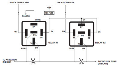
The circuit operates by managing the vacuum pressure required to engage or disengage the pneumatic locking mechanism. It consists of a vacuum source, a control valve, and a locking actuator. The vacuum source is typically connected to the vehicle's engine or a dedicated vacuum pump, which generates the necessary vacuum pressure.
The control valve is an electromechanical component that regulates the flow of vacuum to the locking actuator. It is activated by a switch, which can be integrated into the vehicle's central locking system or operated manually. When the switch is engaged, the control valve opens, allowing vacuum pressure to flow towards the actuator, which then engages the locking mechanism.
The locking actuator is a diaphragm or piston-based device that responds to the applied vacuum. When vacuum pressure is present, the actuator moves, either locking or unlocking the door or trunk. The system is designed to ensure that the locking mechanism operates reliably and efficiently, providing enhanced security for the vehicle.
Additionally, safety features may be incorporated into the design to prevent accidental activation or failure of the locking system. These may include pressure sensors, fail-safe mechanisms, and feedback systems that confirm the locking status. Overall, the single-wire vacuum control circuit is an effective solution for pneumatic locking in high-end automotive applications.The circuit diagram shown below appears one wire vaccum control of pneumatic locking which is popular with Jaguar, Audi and Mercedes Pneumatic 🔗 External reference
Related Circuits
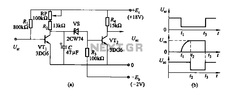
The delay time ranges from 0.5 to 3.5 seconds, which can be adjusted using the potentiometer RP to modify the delay duration. The circuit utilizes a timing mechanism that allows for the adjustment of delay intervals between 0.5 seconds and...
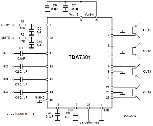
The amplifier is a quad amplifier circuit (amplifier with four inputs and four outputs) based on the TDA7381. This amplifier is designed for car audio systems, but it can also be utilized for other applications. The circuit has a...
With a 1.5V battery supply, the integrated circuit LM3909 can drive the light-emitting diode NSL5027. The 300μF electrolytic capacitor acts as a timing capacitor, which limits the flash speed to approximately 1Hz. The circuit utilizes the LM3909, a popular LED...
The metal detector consists of a probe oscillator, a reference oscillator, an audio amplifier, and various other components, as illustrated in the schematic. The probe oscillator is made up of transistors V1 and V2, a detection coil L1, a...
This power supply utilizes a single 7812 IC voltage regulator along with multiple external pass transistors, enabling it to deliver output load currents of up to 30 amps. The circuit design incorporates a 7812 linear voltage regulator, which is...
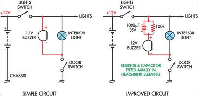
Two headlight reminder circuits are designed for easy installation and operation based on the KISS (Keep It Simple Stupid) principle. The basic circuit consists of a 12V piezo buzzer connected between the lights circuit and a door switch. The...
Warning: include(partials/cookie-banner.php): Failed to open stream: Permission denied in /var/www/html/nextgr/view-circuit.php on line 713
Warning: include(): Failed opening 'partials/cookie-banner.php' for inclusion (include_path='.:/usr/share/php') in /var/www/html/nextgr/view-circuit.php on line 713