
Conducting pipe control one rechargeable short delay circuit
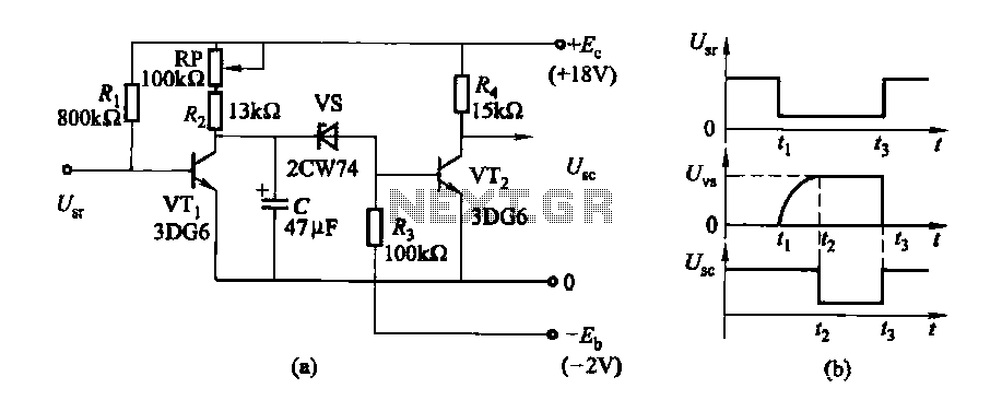
The circuit utilizes a timing mechanism that allows for the adjustment of delay intervals between 0.5 seconds and 3.5 seconds. This is achieved through the integration of a potentiometer, designated as RP, which serves as a variable resistor. By altering the resistance value through the rotation of the potentiometer, the charge time of a timing capacitor in the circuit can be modified, thereby changing the delay time.
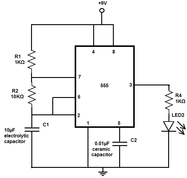
In a typical configuration, the circuit may include a 555 timer IC in monostable mode, where the output pulse width is determined by the equation:
\[ T = 1.1 \times R \times C \]
Here, \( T \) represents the delay time, \( R \) is the resistance (in ohms) set by the potentiometer, and \( C \) is the capacitance (in farads) of the timing capacitor. The choice of capacitor value will influence the maximum and minimum delay times achievable.
To implement this circuit, the following components are typically required:
- A 555 timer IC.
- A potentiometer (RP) for adjusting the delay time.
- A timing capacitor (C) with an appropriate capacitance value.
- Additional passive components such as resistors and diodes may be included for stability and protection.
The output of the circuit can be connected to various devices or indicators, such as LEDs or relays, to visualize or utilize the delayed signal. Proper consideration should be given to the power supply voltage and current ratings of all components to ensure reliable operation.
This circuit design is suitable for applications requiring timed delays, such as in automation systems, timers, or triggering mechanisms.Delay time is 0.5 ~ 3. 5s, adjustment potentiometer RP, can change the delay time.
Related Circuits
The 555 timer chip is a versatile integrated circuit (IC) that, when connected correctly, can generate pulses of current at specific intervals determined by a resistor-capacitor (RC) network. In this mode, the LED does not remain constantly lit; it...
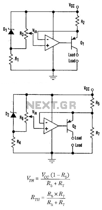
This setup can function as a cost-effective current source with an output accuracy of 1%. However, the voltage offset can activate the current source even when Vqq equals Vin. Modifying the configuration of Figure 1 can resolve the issue...
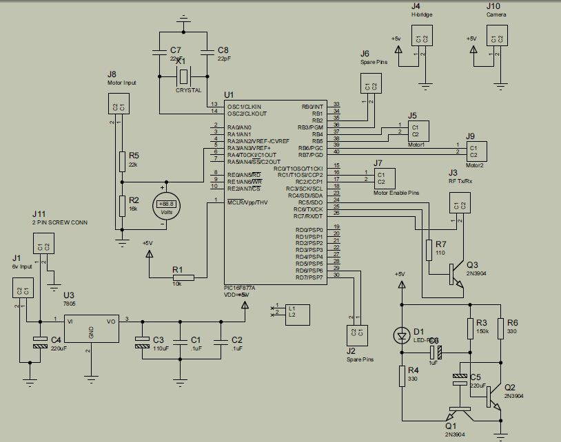
The project is developed by Team Stark, with Gilbert as the leader and team members Martin and Janssen. The tasks have been divided into three parts. The first part includes camera control, login database, installer, and network setup, which...
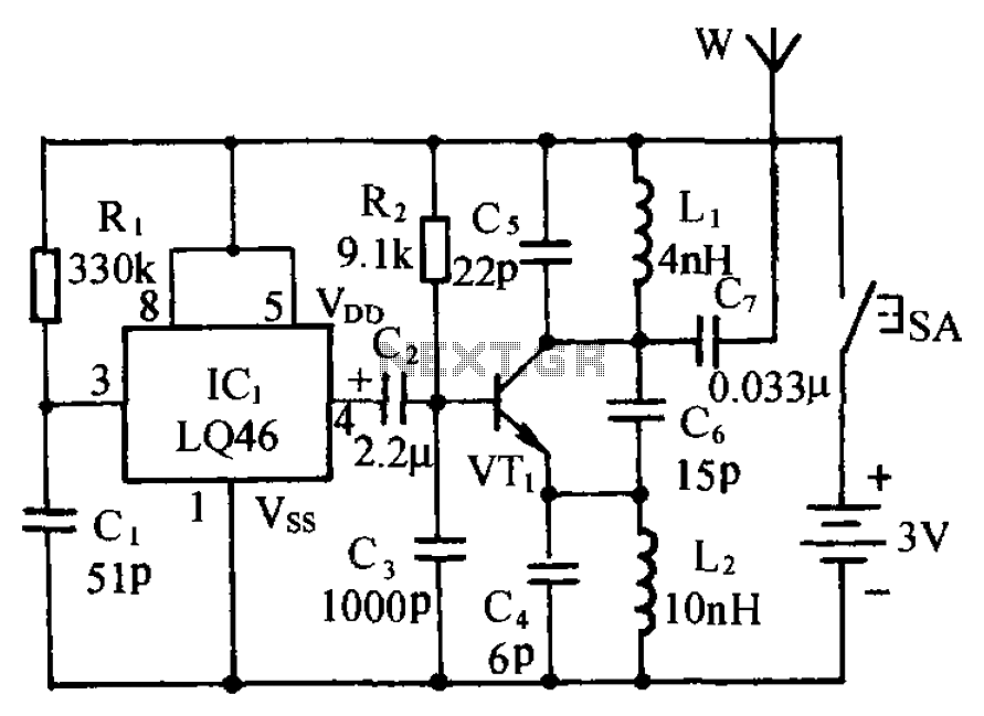
The circuit is presented, consisting of a language and sound circuit FM transmitter. It is simple and easy to manufacture, compatible with ordinary FM radios, allowing for potential listening scenarios and preventive measures. The FM transmitter circuit is designed to...
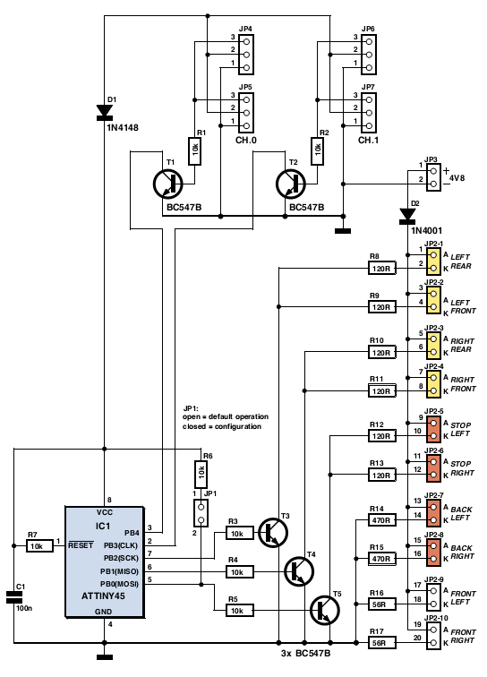
The author gifted a radio-controlled (RC) model car to his partner. She enjoyed it but suggested that adding realistic lights would enhance the experience. Consequently, the author returned to his workshop, utilized his soldering iron, and began outfitting the...
This device is a simple timer that keeps the headlights of a vehicle on for approximately 1 minute and 30 seconds, allowing for illumination when accessing dark areas without the need to return to switch off the lights. Pressing...
Warning: include(partials/cookie-banner.php): Failed to open stream: Permission denied in /var/www/html/nextgr/view-circuit.php on line 713
Warning: include(): Failed opening 'partials/cookie-banner.php' for inclusion (include_path='.:/usr/share/php') in /var/www/html/nextgr/view-circuit.php on line 713