
Schematic Diagram FM Transmitter 4Watt
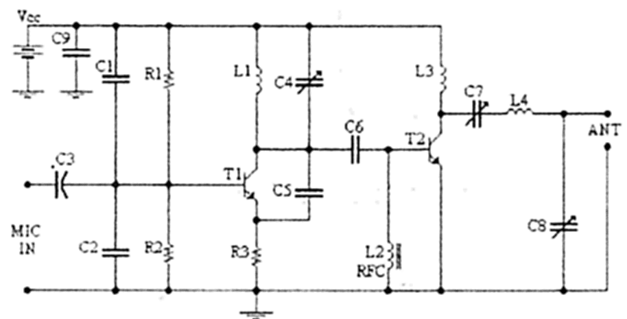
The circuit described involves an L2 RFC (Radio Frequency Choke) with a resistance of 1MΩ, which is crucial for filtering unwanted frequencies and ensuring that only the desired signals are amplified. The inductor is wound with a sufficient number of coils using fine insulated wire, which enhances its inductance and allows for effective energy storage in the magnetic field when current flows through it. The arrangement creates a parallel L-R circuit, where the inductor (L) and the resistor (R) are connected in parallel, enabling the circuit to manage energy dissipation while maintaining the desired frequency response.
The addition of capacitors C7 and C8 plays a vital role in tuning the circuit. These capacitors are used to adjust the overall impedance of the aerial system, allowing for fine-tuning of the circuit to maximize the clarity and strength of the transmitted voice signal. By manipulating their values, the resonance of the circuit can be optimized to ensure that the audio signal is transmitted effectively, reducing noise and enhancing the quality of the received signal. This setup is particularly useful in radio communication applications, where clarity and fidelity of voice transmission are paramount.
In summary, this circuit configuration, with its combination of a high-value resistor, an inductor, and tuning capacitors, is designed to enhance radio frequency performance, ensuring that voice signals are transmitted and received with optimal clarity.L2 RFC (resistance 1MOhm with wrapped around her inductor of enough coils from fine isolated wire. Scratch of utmost inductor and you stick in utmost the resistance making thus a parallel L-r circuit. ) With their C7, C8 we adapt the resistance of aerial (practically to them we regulate so that it is heard our voice in the radio as long as you beco
me cleaner). 🔗 External reference
Related Circuits
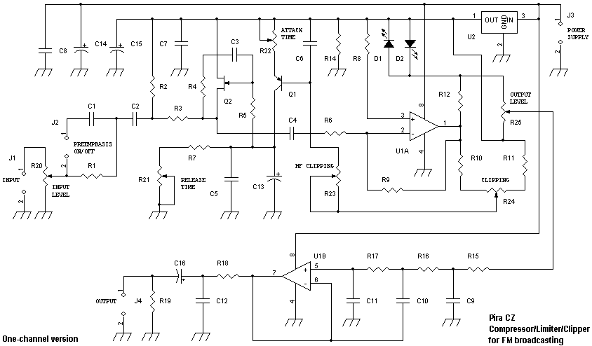
Audio signals as music or speech have big dynamic ranges. There are silent and loud sections. These audio signals aren't too good for a transmitter, which requires audio signal with constant level on the input. Limiter is a device,...
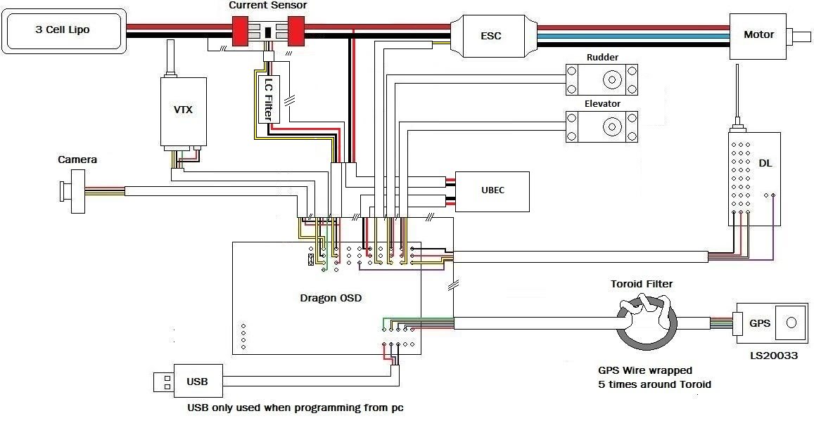
A discussion has been initiated regarding the diagrams being created. The initial set pertains to the DOSD (Dual OSD). Following the discovery of a potential issue, these new diagrams will facilitate safe wiring of the DOSD, thereby avoiding the...

A simple technique for measuring frequencies across a wide range with acceptable accuracy limits using a PC is presented. This method follows the basic principle of measuring low frequencies, where the period of a complete wave is measured and...
A 1.5 Volt tracking transmitter utilizing simple circuits. The current draw for this tracker is 3.7 mA, allowing the 1.5V button cell to have a prolonged lifespan. The 1.5 Volt tracking transmitter is designed to operate efficiently with a low...
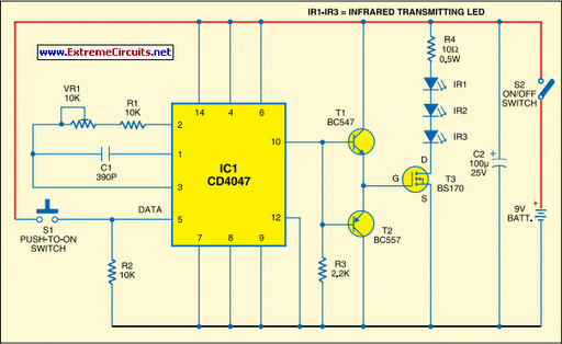
Most IR remotes operate reliably within a range of 5 meters. The complexity of the circuit increases when designing an IR transmitter for reliable operation over a longer range, such as 10 meters. To double the range from 5...
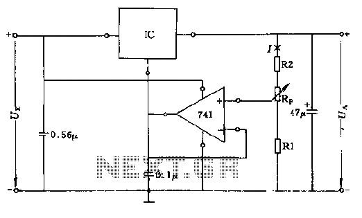
The circuit consists of resistors R1, R2, and RP, where the resistance values play a critical role in determining the magnitude of the current I. This current must exceed the input current of the operational amplifier, which is approximately...