
Automotive Wiring Diagrams
The electrical wiring diagrams provided for various vehicles serve as essential tools for understanding and troubleshooting automotive electrical systems. Each diagram illustrates the relationships between components, highlighting their functions and interconnections. For example, in the 1986 Ford Bronco and F-Series Pickup, the beam select switch controls the headlights, while the ignition coil is crucial for starting the engine. The vehicle speed sensor provides real-time data to the vehicle's computer for speed regulation and performance monitoring.
In the rear window wiring of the 1957-58 Ford Mercury Sedan, the instrument panel control switch allows the driver to operate the rear window, while the backup window motor enables the window to move up and down. The circuit breakers included in the diagram protect the electrical system from overloads, ensuring safe operation.
The transmatic transmission wiring diagrams for the 1964 Ford trucks illustrate the complexity of the transmission system. The starter relay initiates the starting process, while the neutral switch prevents the vehicle from starting in gear. The transmission selector dial light provides visual feedback to the driver regarding the selected gear.
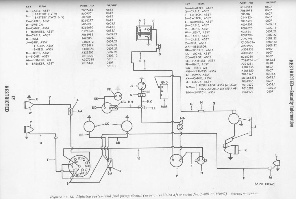
The fuel pump schematic for the 1964 Ford trucks distinguishes between single and dual tank configurations, which is critical for vehicles that may have different fuel delivery systems. Components such as the fuel pump safety switch and circuit breakers ensure the safe operation of the fuel system, preventing electrical failures that could lead to fuel leaks or engine stalls.
The car cooling system is a critical component that maintains engine temperature within operational limits. The water pump circulates coolant through the engine and radiator, while the thermostat regulates coolant flow based on temperature, ensuring efficient engine operation. The sealed system design allows for higher boiling points of the coolant, preventing overheating and potential engine damage.
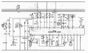
Finally, the wiring diagrams for the Ford Lincoln Continental models provide a comprehensive overview of the electrical systems, detailing essential components that facilitate vehicle operation. Understanding these diagrams is crucial for any maintenance or repair work, ensuring that all connections are made correctly and safely. The electrical wiring diagram for the Suzuki VS750 Intruder similarly outlines key components necessary for the motorcycle's operation, emphasizing the importance of familiarity with the schematic for effective troubleshooting and repairs.What you will be seeing here is a circuit diagram about the electrical wiring diagram of the 1986 Ford Bronco and F-Series Pickup. Please make sure you have read and understand about the electrical wiring diagram shown here first before making any wiring changes on your Ford Bronco and F-Series Pickup.
About the parts you will see inside is like: beam select switch, impact switch, ignition coil, vehicle speed sensor, power steering switch, windshield wiper motor, etc. (click image to enlarge) A schematic that will be shown here will be about the rear windows wiring diagram of the 1957-58 Ford Mercury Sedan.
There are parts to deal with and connections to understand, so be sure to have read and comprehend this rear window wiring diagram first before you make any wiring changes on your For Mercury Sedan. The parts are like: instrument panel control switch, backup window motor, 15 amp circuit breaker, ignition switch, window regulator safety relay, and 30 amp circuit breaker.
(click image to enlarge) We will now show you the transmatic transmission wiring diagrams of the 1964 Ford B-, F-, and T-Series Trucks. This schematic shows a very clear image, you can see each parts and their connections. Some of the components here are like: starter relay, neutral switch, transmission selector dial light, transmission retarder oil temperature warning light, retarder oil temperature warning switch, ignition switch, and relay.
(Click image to enlarge) The following table outlines the most common used wire colors for Toyota vehicles manufactured between 1975-2006. Please note that it is very important that you test, confirm and verify all wiring with a test meter prior to making any connections or repair.
What we`ll show you here is the fuel pump schematic diagrams of the 1964 Ford B-, F- and T-Series Trucks. This schematic diagrams shows two different tank types, the single tank and the dual tank. Some components inside are as following: battery positive terminal, fuel pump safety switch, 70-amp circuit breaker, fuel pump primer switch, starter relay, ignition switch, fuel pump, fuel tank sending unit, fuel gauge, etc.
(Click image to enlarge) Now below you will see how car cooling system works by sending a liquid coolant through passages in the engine block and heads. As the coolant flows through these passages, it picks up heat from the engine. The heated coolant then passes through a rubber hose to the top inlet of the radiator in front of the car.
The coolant flows down through the thin tubes in the radiator; the hot coolant is cooled by the air stream entering the engine compartment from the grill in front of the car. Once the coolant has made its way to the bottom of the radiator and is cooled it returns to the engine through a rubber hose to absorb more heat.
The water pump has the job of keeping the fluid moving through the entire system. On most cars today the radiator is made of thin aluminum tubes with aluminum fins that zigzag between the tubes. Air is pulled through the fins via cooling fans causing the heat in the radiator to be transferred into the air stream and carried away from the vehicle.
The radiator has two tanks, one for inlet of heated coolant and the other for outlet of the cooled fluid. The cooling system is sealed. When the coolant gets hot it expands and causes an increase in pressure in the cooling system. When coolant is under pressure the boiling point of the liquid becomes higher. Coolant is made with ethylene glycol, which has a higher boiling point than water, along with keeping it under pressure allows the coolant to safely reach temperatures in excess of 250 degrees.
The pressure cap is a simple device that will maintain the pressure in the system to a certain point. If the pressure builds up higher than the set pressure point there is a spring loaded valve that allows the pressure to release.
During this process a small amount of coolant is bled off into the Reservoir tank which is not pressurized. Since there is less coolant in the system, as the engine cools down a partial vacuum is formed. The radiator cap on these closed systems has a secondary valve to allow the vacuum in the cooling system to draw the coolant back into the radiator from the reservoir tank.
A water pump is a simple device that will keep the coolant moving through the system as long as the engine is running. The pump is driven by either a fan belt which usually drives another component, a serpentine belt which drives all components, a timing belt, or in some cases gear driven.
The thermostat is simply a valve that measures the temperature of the coolant and, if it is hot enough, opens to allow the coolant to flow to the radiator. If the coolant is not hot enough, the flow to the radiator is blocked and fluid is directed back to the engine via a bypass system.
Because flow to the radiator is blocked, the engine will reach operating temperature sooner and, on a cold day, will allow the heater to begin supplying hot air to the interior more quickly. The hot coolant is also used to provide heat to the interior of the vehicle when needed. The heater core looks like a small version of a radiator, connected to the cooling system with a pair or rubber hoses.
One hose brings hot coolant to the heater core and the other hose returns the coolant back to the engine. A fan called a blower, draws air through the heater core and directs it through the heater ducts to the interior of the car.
Temperature of the heat is regulated by a blend door that mixes cool outside air or air conditioned air with the heated air coming through the heater core. Check to see if any green, orange, or yellow fluid is leaking from under your vehicle. If it is you are probably losing coolant and should get it inspected. Our technicians inspect your cooling system as part of our famous 30-Point Inspection that they perform during every service visit.
Your cooling system should be serviced annually to prevent overheating that can severely damage your engine. What We Inspect: If you have read the Wiring Diagrams Of 1962 Ford Lincoln Continental Part 1, now let us take you to see the wiring diagrams of the 1962 Ford Lincoln Continental part 2.
The wiring diagrams also contains many different parts and connections to comprehend before you can do any wiring work properly with you car`s wiring systems, and the parts are like: current regulator, high beam, direction signal, low beam, starter, generator, coil, oil pressure switch, cutout relay, right blower motor, horn relay, etc. (click image to enlarge) What we will discuss here is the schematic or the wiring diagrams of the 1961 Ford Lincoln Continental part 1.
Go HERE for the part 2 of the wiring diagrams. Inside, we will see many components and connections, the components or parts will be like: instrument light, instrument cluster connector, ignition switch, parking brake warning light & switch, door lock warning light, transmission dial light, direction signal switch, horn, etc. (click image to enlarge) The next schematic is about the wiring diagrams of the 1960 Ford Lincoln and Continental part 1.
See the part 2 of the wiring diagrams HERE. As usual, we must advise you to first read and comprehend both parts of the wiring diagrams before performing any wiring work with your Ford car`s wiring systems. In this first part you will see many components like: tail light, stoplight & direction signal, left backup light, left reading & switch, ashtray light, instrument cluster connector, light switch, parking brake, warning light & switch, left direction indicator, constant voltage regulator, speedometer lights, selector dial light, direction signal switch, high beam indicator, etc.
(click image to enlarge) Next, we will be discussing about the electrical wiring diagram of the 1988-1991 Suzuki VS750 Intruder for US and Canada release part 1. There will be two parts of the wiring schematic, to access the part 2 you can see them HERE. Inside this first part Suzuki VS750 Intruder electrical wiring diagram you can see parts like: front turn signal, water temperature unit, water temperature indicator light, oil indicator light, high beam indicator light, turn signal indicator light, motor light, headlight, diode, water temperature gauge, dimmer switch, horn button, clutch switch, neutral switch, oil switch, etc.
🔗 External reference
Related Circuits
This section describes the components of the receiver, which includes the post-mixer amplifier, variable crystal filter, intermediate frequency (IF) amplifier, product detector, local oscillator, receiver muting, and audio amplifier. The transmit section features the local oscillator, transmit single balanced...
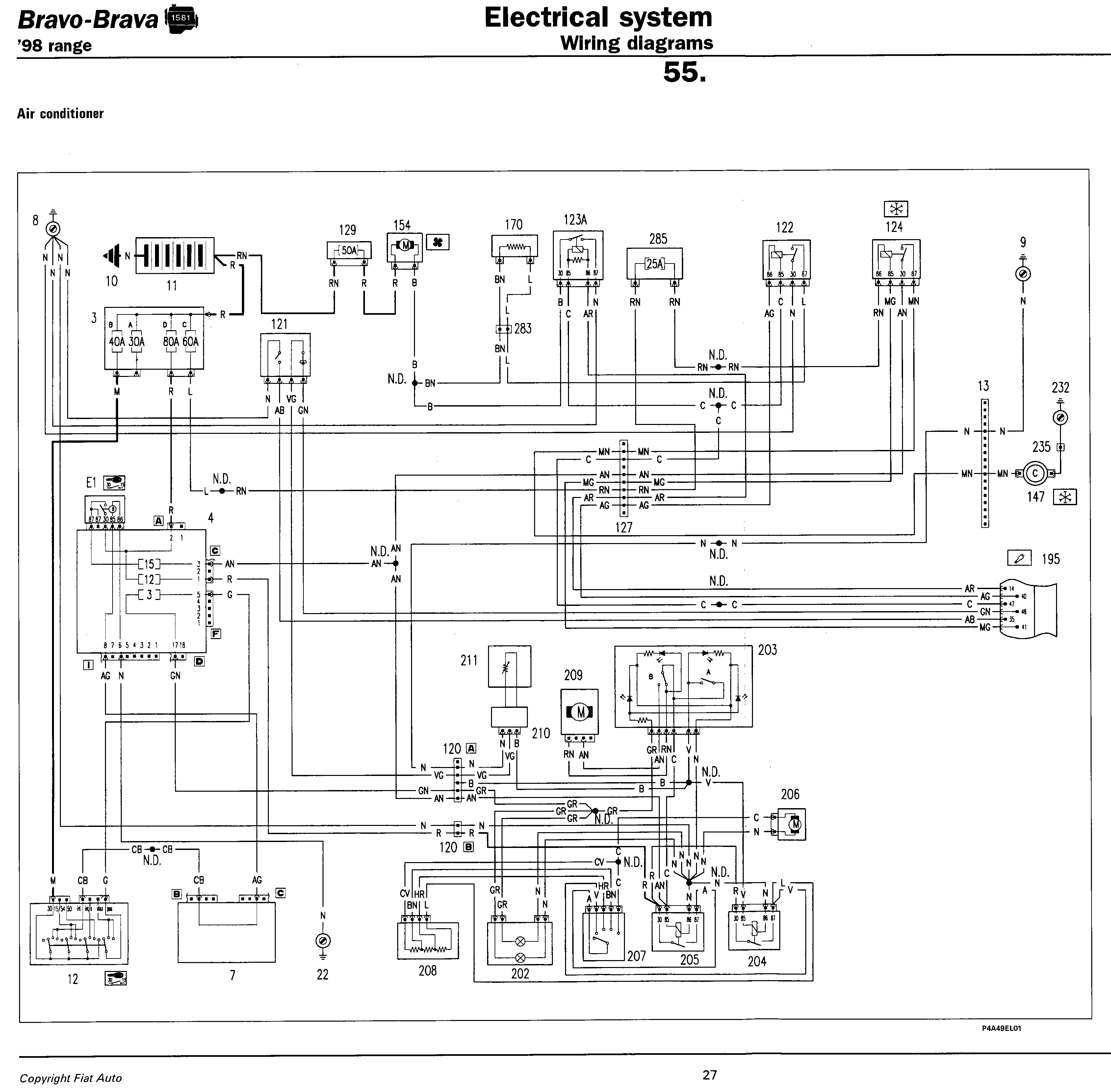
Fiat Punto Wiring Diagram Manual PDF Download. The Fiat Punto Wiring Diagram Manual provides essential information for understanding the electrical systems of the Fiat Punto model. This manual typically includes detailed wiring diagrams, pin configurations, and color codes for various...
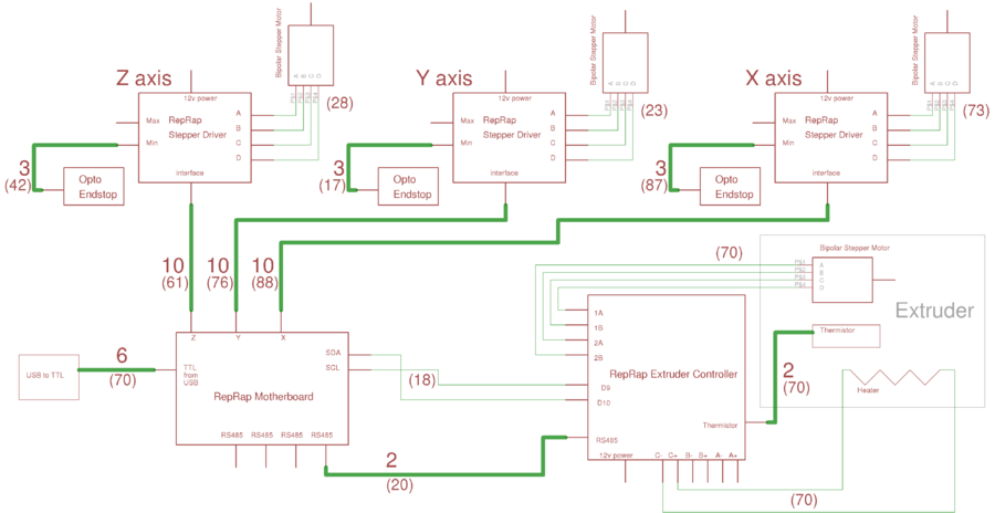
This page outlines the wiring procedure for the RepRap Version II "Mendel." Prior to connecting the machine, it is essential to test the circuit boards individually, as detailed on this page. The overall Mendel wiring diagram is available; clicking...
The following document contains information related to the electrical installation schematic diagram for the Volvo 440. It includes the wiring schematic for the Volvo 440, 460, and 480 series. The Volvo 440, 460, and 480 series vehicles feature a comprehensive...

The most likely issue with the wiring is the individual responsible for it. Apologies for the lengthy post, but providing more information and pictures may help clarify the situation. To create a comprehensive electronic schematic description, it is essential to...
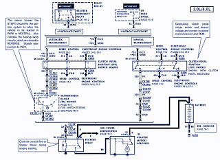
The part of the 1995 Ford Ranger wiring diagram includes components such as the transmission range sensor, electronic engine control, clutch pedal position switch jumper, speed control, automatic transmission, starter interrupt relay, relay box, starter motor during engine starting,...