This page outlines the wiring procedure for the RepRap Version II "Mendel." Prior to connecting the machine, it is essential to test the circuit boards individually, as detailed on this page. The overall Mendel wiring diagram is available; clicking the image provides a full-resolution version. The wiring diagram can be found as an Eagle schematic in the download folder at mendel/electronice/mendel-wiring-diagram.sch. The latest version is accessible in the RepRap subversion repository, though it may be an unstable development version. In the diagram, multi-way connections are represented by thick lines with a corresponding number indicating the number of wires in the connection. Numbers in brackets denote the lengths of the wires in centimeters. Thin lines indicate single wires. To maintain clarity, the power wiring is not depicted in the diagram; however, it is straightforward. The 12 volts from the Mendel USB and power connector are connected in parallel to the three stepper driver boards and to all extruder controller boards. The motherboard does not require connection to Mendel's internal power connectors, as it is powered via the USB connection from the computer. The extruders are connected in parallel to the RS485, SDA, and SCL ports on the motherboard. Although the system has only four connectors for these on the motherboard, chaining is possible up to a reasonable number; theoretically, it could support up to 64 extruders simultaneously. The image above illustrates the socket (female) and pins (male). Pin 1 serves as the ground (negative) connection, while pin 2 is the +12V connection. Pin 3 is unused. Mendel includes a panel-mounted male plug connector. Wires of different colors capable of handling 8 amps should be utilized. If the wires are not twisted or paired, they can be twisted manually by securing one end in a vice and the other end in a hand twist-drill chuck and winding. All wires should be twisted simultaneously before cutting. A four-way "chocolate-block" connector should be attached beside the XLR power input. Additional 3mm holes may need to be drilled in the stepper plate, depending on the connector's hole gaps. Two short wires should be soldered to the XLR power connector, measured to the two central connections in the chocolate-block. After untwisting, heat shrink should be applied to the terminals before twisting them again. Two small U-shaped wire pieces are required to connect the two central chocolate-block connectors to the outer ones. All wires should be placed in the block, but the screws should not be tightened yet. The extruder stepper is governed by the extruder controller, while the motherboard communicates directly with the stepper drivers on the extruder board using the SCL/SDA pins on the motherboard and the D9/D10 connections on the extruder controller. The connection between the motherboard and extruder board is depicted in the following image. When assembling ribbon cables for the stepper control boards, 10-way insulation-displacement connectors (IDCs) should be used. A pair of these connectors should be oriented in the same direction; when laid flat, the projecting tabs on the IDC connectors that align with the sockets on the boards should face the same way. Attaching an IDC connector to a ribbon cable can be accomplished with a standard vice, eliminating the need for specialized tools. The cable should be pushed through the connector until it extends approximately 2 mm on the other side. It is important to ensure that the cable is square and not angled. After loosely pushing the connector together by hand, it should be placed in a vice and tightened gently to establish the connection. The 2 mm projecting wires should be trimmed carefully with a sharp blade to avoid leaving wire threads that could cause short circuits. The wires connecting the X stepper motor to its control board are relatively long; extensions may need to be soldered onto the stepper. The stepper wires should be cut to a length of about 50 mm, with the ends bared and lengths of heat-shrink tubing applied to them. The ends of a 4-way ribbon cable should also be stripped.This page describes how to wire up RepRap Version II "Mendel". Before you wire the machine up, test the circuit boards individually as described on this page. This is the overall Mendel wiring diagram; click the image for a full-resolution version. The wiring diagram is stored as an [ Eagle ] schematic in your download at mendel/electronice/mendel -wiring-diagram. sch. The latest version is in the [ RepRap subversion repository here ], but that may be an unstable version in development. In the diagram above multi-way connections are shown as thick lines with a number next to them. The number is the number of wires in the connection. Numbers in brackets are the lengths of the wires in centimeters. Thin wires are single wires. The power wiring is not shown on the diagram for clarity, but it is very simple. The 12 volts from the Mendel USB and power connector is connected in parallel to the three stepper driver boards and to all the extruder controller boards.
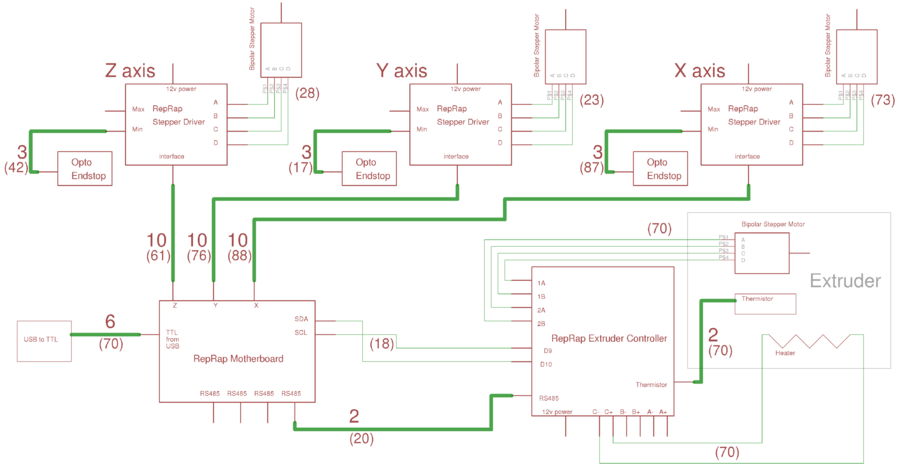
The Motherboard does not need to be connected to Mendel`s internal power connectors. It is powered by the USB connection from the computer. The extruders are connected in parallel to the RS485 and to the SDA and SCL ports on the Motherboard. The system only has four connectors for these on the Motherboard, but you can chain these together up to any reasonable number (in theory it should be possible to drive 64 extruders at once.
). The picture immediately above is looking into the socket (female) and at the pins (male). Pin 1 is the ground (negative) connection and pin 2 is +12v connection. Pin 3 is not used. Mendel has a panel-mounted male plug connector. Use wires of different colours that are capable of taking 8 amps. If your wires are not twisted or paired you can easily twist them up yourself by putting one end of the pair in a vice, the other end in a hand twist-drill chuck, and winding. Do all the wire at once, then cut it. Attach a four-way "chocolate-block" connector beside the XLR power input. You may need to drill a couple of extra 3mm holes in the stepper-plate, depending on the hole-gaps in your connector.
Solder two short wires to the XLR power connector as shown. Measure them to the two central connections in the chocolate-block. Then untwist them, put heatshrink on the terminals, and twist them up again. Make two small U-shaped pieces of wire to attach the two central chocolate-block connectors to the two outside ones. Put all the wires in the block, but don`t tighten the screws yet. The extruder stepper is controlled by the extruder controller. But the motherboard talks directly to the stepper drivers on the extruder board, using the scl/sda pins on the motherboard and the d9/d10 connections on the extruder controller.
The following image shows how the motherboard and extruder board are connected. When making up ribbon cables for the stepper control boards us 10-way insulation-displacement connectors (IDCs) on the ribbon cables. A pair of these should be the same way round. That is to say, when you put the cable flat on the bench, the projecting tabs on the IDC connectors that key with the sockets on the boards should both point the same way.
It is simple to put an IDC connector on a ribbon cable using an ordinary vice. You don`t need a special tool. Push the cable through the connector so that it projects about 2 mm clear on the other side. Check that it is square and not at an angle. Push it together loosely by hand, then place it between the jaws of a vice. Tighten the vice gently to make the connection. Finally trim the 2mm projecting wires with a sharp blade making sure that you don`t leave wire threads shorting. The wires between the X stepper motor and its control board are quite long. You may need to solder extensions onto the steppper. Cut the stepper wires off at a length of about 50 mm, bare the ends, and put lengths of heat-shrink on them.
This electronic timer switch will turn on a light for 100 seconds, turn it off for another 100 seconds, and then turn it on again for 100 seconds after an hour of powering up the circuit. It is a...
Voltage inverter circuit design electronic project using few electronic components
The voltage inverter circuit is a fundamental electronic project that converts direct current (DC) to alternating current (AC). This circuit is particularly useful in applications where AC voltage is required...
An example of an electronic metronome schematic is presented. The electronic metronome is popular due to its simplicity and compact size.
The electronic metronome schematic typically consists of several key components that work together to produce a rhythmic sound at...
This circuit consists of twin-T sine-wave oscillators. Each oscillator has a filter in the feedback loop. If the loop gain is greater than unity, the circuit will oscillate. Gain is adjusted to be just less than unity. Touching the...
The alarm will switch off when the 4 keys connected to "A,B,C,D" are pushed in the right order. The circuit works because each gate stands upon its predecessor. If any key other than the correct key is pushed, then...
The Elect. Sel. 8 is a simple circuit, with a choice of 8 sources of any sort, of 8 independent switches. Each switch corresponding with a relay for example the switch S1 activates the RL1 etc. The uses of...
We use cookies to enhance your experience, analyze traffic, and serve personalized ads.
By clicking "Accept", you agree to our use of cookies.
Learn more