
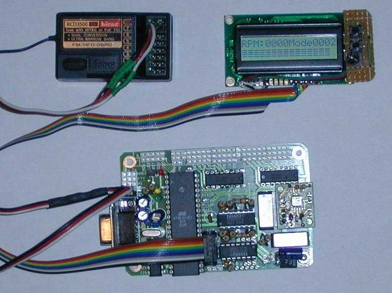
autopilot with rev 2.2 board
The gyro filters consist of:
14 DIP socket and OPA432 op amp 2 * 0.1 uF capacitor 2 * 1.0 k Ohm 2 * 4.7 k Ohm 2 * Tokin CG-16D Note that the orientation pin on the Tokin gyro is larger than Murata, so you will have to remove the pin or enlarge the mounting hole. Be careful when you solder the gyros onto the board -- too much heat can desolder the pin inside the gyro. Finish populating the headers, including the LCD, the sensor inputs and so on. Add the two LEDs (not supplied) with yellow into 3 and green into 4; the longer lead is for power and goes into the left hole. The LEDs require a step-down, so solder a 1.0 k Ohm resistor in the two holes to the left of LED #3. The PPM decoder uses an NPN transistor (not included) in the three holes. They are (from left to right) emitter, base, collector. When correctly oriented, the flat side of the transistor should face south. Just below the transistor are two holes for a 1.0 k Ohm resistor. The pitch and roll accelerometer filters are identical. Each consists of one opamp follower to buffer the output and a low pass filter with 3.2 times gain. The reference voltage is generated by a voltage divider that outputs Vcc/2 since the nominal output of the accelerometers is 50%. The components are: 2 * 33 k Ohm (feedback stage 1) 2 * 22 k Ohm (feedback stage 2) 2 * 6.8 k Ohm 2 * 1.0 k Ohm (voltage divider) 2 * 0.1 uF
Attach the accelerometer (not included). Either use the ADXL202-EB in the five through holes as shown, or surface mount an ADXL202-E. If you use the -EB model, you'll have to connect the Cfilt pins on the -EB to the holes labeled "X" and "Y" above the Cfilt holes. The easiest way to do this is to leave the long leads closest to the chip on the capacitors when you solder them to the -EB. When you start to solder the -EB to the Rev 2.2 board slide the leads through the holes marked "X" and "Y" above the Cfilt label. I haven't been able to get a good picture of this yet. The digital outputs are not used with the Rev 2.2 board. The yaw gyro uses the same filter circuit as the other two. It also needs a jumper to connect the output of the opamp (labeled "Yaw") to the ADC input on the ATmega (labeled "Yaw" as well). The case is US$1.99 from the Container Store and makes it "iMAC compatible"... Zoom in on the image to see the highlighted solder points. The yaw gyro does require some tricks to mount. This is just a serving suggestion; we've also successfully mounted it to the side of the case. The small PCB is cut from a RadioShack part. I used a length of four conductor phone wire for the jumper.
The circuit design incorporates two 4017 decade counters, which serve as the primary control elements for the servo driver. The configuration allows for the flexibility of using either the A side headers or the optional B side headers, depending on the number of headers received. The power supply connections are critical, necessitating careful trace cutting and jumper soldering to ensure proper functionality.
The gyro filters are essential for stabilizing the pitch and roll data. Each filter is built around an OPA432 op amp and includes a combination of capacitors and resistors to form low-pass filter circuits, which help in smoothing the sensor outputs. The selection of components, such as the Tokin CG-16D gyros, requires attention to orientation during installation to prevent damage.
LED indicators are incorporated into the design to provide visual feedback, with the need for current-limiting resistors to ensure proper operation. The PPM decoder utilizes an NPN transistor for signal processing, and its correct orientation is crucial for the circuit's performance.
The accelerometer filters are designed to buffer the output and provide necessary gain, with a voltage divider to ensure the reference voltage matches the expected output of the accelerometer. The assembly of the accelerometers, whether using the ADXL202-EB or surface-mounted options, requires careful consideration of lead length and positioning to ensure proper connections.
The yaw gyro filter circuit mirrors that of the pitch and roll filters, with additional jumper connections required for interfacing with the ATmega ADC inputs. Overall, this schematic emphasizes careful component selection, orientation, and soldering techniques to achieve a fully functional servo driver and sensor interface.The servo driver is just simply two 4017 decade counters and lots of 0.1" headers. Only populate the A side headers; the B servo bank is optional and will require a few more header pieces. If you received 20 headers, you'll be short two of them. If you received 25 headers, go ahead and fill it up. You will have to cut the headers to get the 2 pin header for the power supply. There is a mistake (sorry!) in the 4017 power supply. You have to cut the two traces and solder on a jumper as shown. Zoom in to see the trace on the bottom that needs to be cut. The corresponding trace on the top also has to be cut. Zoom in on the next image to see the one to cut on top. Be sure that they are both fully severed; otherwise you will short the power supply and things won't work.
After testing the first pieces, the next step is to add the pitch and roll gyro filters. I apologize for the larger 1/2 W resistors -- I messed up on my DigiKey order. You can subsitute RadioShack 1/4 W 5% or 1/4 W 1% items if you have trouble fitting it together. Note the orientation of the opamp -- it is upside down relative to the one above it. The silk screen image and schematic show it correctly. The schematic shows the yaw gyro filter as well, but for space reasons you may wish to wait until the yaw gyro connection is soldered inplace before attaching the filter components. The gyro filters consists of: 14 DIP socket and OPA432 op amp 2 * 0.1 uF capacitor 2 * 1.0 k Ohm 2 * 4.7 k Ohm 2 * Tokin CG-16D Note that the orientation pin on the Tokin gyro is larger than Murata, so you will have to remove the pin or enlarge the mounting hole.
Be careful when you solder the gyros onto the board -- too much heat can desolder the pin inside the gyro. Finish populating the headers, including the LCD, the sensor inputs and so on. Add the two LEDs (not supplied) with yellow into 3 and green into 4; the longer lead is for power and goes into the left hole.
The LEDs require a step-down, so solder a 1.0 k Ohm resistor in the two holes to the left of LED #3. The PPM decoder uses an NPN transistor (not included) in the three holes. They are (from left to right) emitter, base, collector. When correctly oriented, the flat side of the transistor should face south. Just below the transistor are two holes for a 1.0 k Ohm resistor. The pitch and roll accelerometer filters are identical. Each consists of one opamp follower to buffer the output and a low pass filter with 3.2 times gain. The reference voltage is generated by a voltage divider that outputs Vcc/2 since the nomimal output of the accelerometers is 50%. The components are: 2 * 33 k Ohm (feedback stage 1) 2 * 22 k Ohm (feedback stage 2) 2 * 6.8 k Ohm 2 * 1.0 k Ohm (voltage divider) 2 * 0.1 uF Attach the accelerometer (not included).
Either use the ADXL202-EB in the five through holes as shown, or surface mount an ADXL202-E. If you use the -EB model, you'll have to connect the Cfilt pins on the -EB to the holes labeled "X" and "Y" above the Cfilt holes. The easiest way to do this is to leave the long leads closest to the chip on the capacitors when you solder them to the -EB.
When you start to solder the -EB to the Rev 2.2 board slide the leads through the holes marked "X" and "Y" above the Cfilt label. I haven't been able to get a good picture of this yet. The digital outputs are not used with the Rev 2.2 board. The yaw gyro uses the same filter circuit as the other two. It also needs a jumper to connect the output of the opamp (labeled "Yaw") to the ADC input on the ATmega (labeled "Yaw" as well).
The case is US$1.99 from the Container Store and makes it "iMAC compatible"... Zoom in on the image to see the highlighted solder points. The yaw gyro does require some tricks to mount. This is just a serving suggestion; we've also successfully mounted it to the side of the case. The small PCB is cut from a RadioShack part. I used a length of four conductor phone wire for the jumper. 🔗 External reference
Related Circuits
This data sheet describes the evaluation board for the AD9834 direct digital synthesizer (DDS). The AD9834 is a numerically controlled oscillator that utilizes a phase accumulator, a sine look-up table, and a 10-bit DAC. The AD9834 can operate with...
This board is designed specifically to control the 5-motor Robot Arm sold by Baycom Technologies. It has no input facilities, but it is less expensive than combining the I/O Board with the Relay sub-Board. If you need lots of...
The circuit depicted in Figure 3-168 utilizes a controller for speed grading and reversing control. A reverse brake is connected to the rotor circuit through an overcurrent relay, labeled KI, for control. The current relay KIi to KI3 serves...
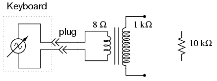
An electronic musical keyboard serves as a source of variable-frequency AC voltage signals. It is not necessary to purchase an expensive keyboard; a model with at least a few dozen voice selections (such as piano, flute, harp, etc.) is...
Most individuals seeking to modify and enhance their Spectrum often focus on the keyboard as a primary area for improvement. However, a straightforward replacement requires opening the computer, which can be discouraging for two main reasons. Firstly, this action...
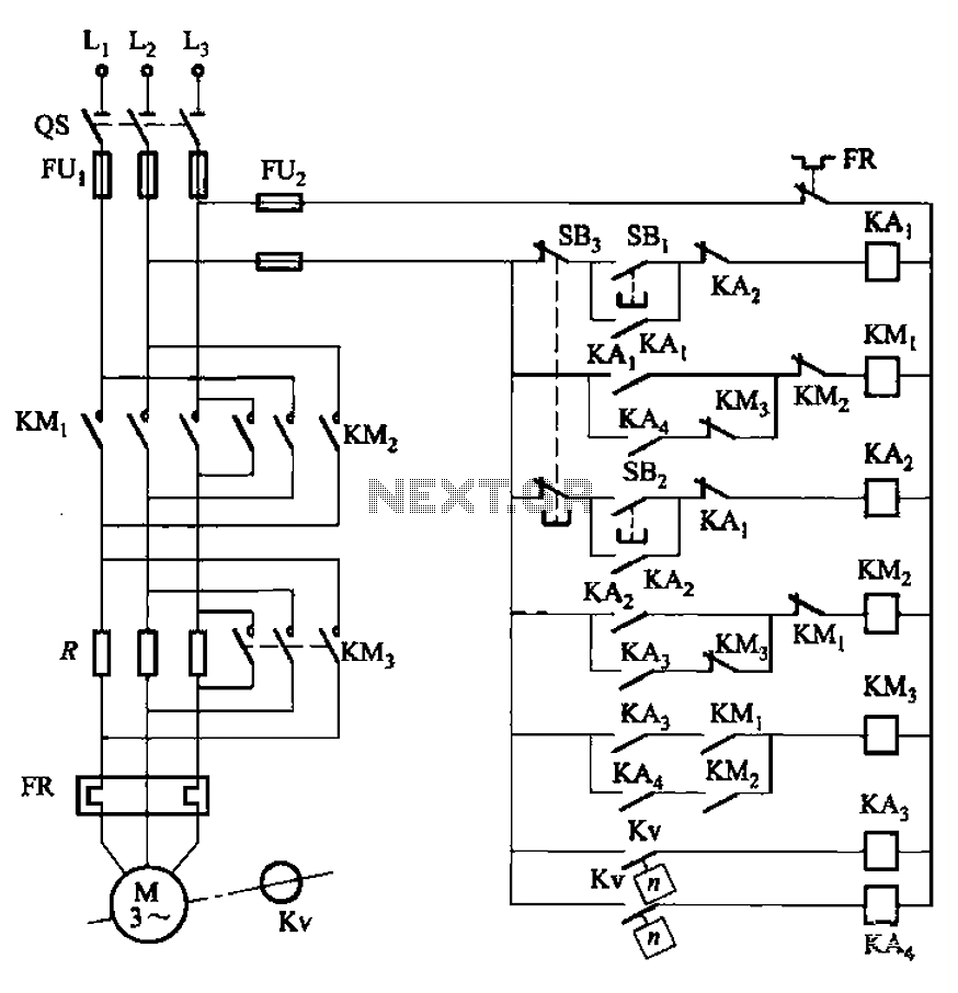
The circuit illustrated in Figure 3-130 differs from the circuit in Figure 3-129 in that when the stop button SB3 is pressed, the electric motor initiates braking. Furthermore, during both the startup and braking phases, the motor power lines...