
PC 8Way Relay Board
Optional: 8 x 3way PCB mounted terminal mounts.
Kit Assembly:
Begin with the smaller items such as the 1N914 diodes and then the IC. You can then start on the 'taller' items like LEDs, resistors, regulator, bridge, green cap, etc. Once you have the basic components soldered in, carefully install the DB25 socket. Make sure that none of the pins get bent over as you're trying to wiggle everything into place. It's a nightmare to unsolder the socket if you make a mistake! Leave the relays until last.
Any 12 -15 volt 1 amp minimum AC or DC power supply can be used.
The control board is designed for a specific application, facilitating the operation of a 5-motor robot arm through the use of relays. The absence of input facilities indicates that this board is primarily focused on output control, making it a cost-effective solution for users requiring multiple relay outputs without the need for additional input functionalities.
The board features a printed circuit board (PCB) that houses various components. It includes eight single-pole double-throw (SPDT) relays, each rated for 12 volts, which are responsible for controlling the motors of the robot arm. The relays are activated by signals sent from the ULN2803 integrated circuit, which serves as a relay driver capable of controlling multiple outputs from a lower input voltage.
Power management is facilitated by the LM7812 voltage regulator, which ensures a stable output voltage of 12 volts from a higher input voltage, accommodating a range of 12 to 24 volts as specified. The bridge rectifier converts AC input power to DC, and the presence of diodes (1N4004 and 1N914) protects the circuit from back EMF generated by the relays and motors, ensuring reliability and longevity of the components.
LED indicators are included to provide visual feedback on the operational status of the relays, with current-limiting resistors ensuring proper operation without damaging the LEDs. The electrolytic capacitor (47uF) serves as a filter to smooth out voltage fluctuations, while the optional terminal mounts provide the flexibility for additional wiring configurations.
The assembly process is straightforward, starting with the smaller components to avoid complications when soldering larger components later. Special care should be taken during the installation of the DB25 socket to prevent pin damage, which can complicate repairs. The recommended power supply is crucial for ensuring the board operates efficiently, with a minimum of 1 amp current rating to support the relay activation and motor operation.
Overall, this control board represents a practical solution for users looking to manage multiple motors in a robotic application, emphasizing ease of assembly, cost-effectiveness, and robust performance.This board is designed specifically to control the 5-motor Robot Arm sold by Baycom Technologies. It has no input facilities, but it is less expensive than combining the I/O Board with the Relay sub-Board. If you need lots of relays and no input, this is the way to go. Parts List: 1 x PCB 8 x SPDT 12 volt Relays 1 x PCB mounted DB 25 Socket 1 x ULN2803 Integrated Circuit 1 x 1N4004 Diode 8 x 1N914 Diode 8 x 3mm Red LED 8 x 560 ohm 1/4 watt resistor 1 x 47uF Electrolytic Capacitor (up to 1000uF can be used depending on the power supply) 1 x 0.01uF (approx) Green Cap 1 x LM7812 Voltage regulator (T220 case) 1 x 1 amp Bridge Rectifier 1 x 2.1mm Power Socket 25 pin Serial Cable - Male to Male 12 - 24 volt power supply with 2.1mm Plug Optional: 8 x 3way PCB mounted terminal mounts. Kit Assembly: Begin with the smaller items such as the 1N914 doides and then the IC. You can then start on the 'taller' items like LEDs, resistors, regulator, bridge, green cap, etc. Once you have the basic components soldered in, carefully install the DB25 socket. Make sure that none of the pins get bent over as you're trying to wiggle everything into place. It's a nightmare to unsolder the socket if you make a mistake! Leave the relays until last. Any 12 -15 volt 1 amp minimum AC or DC power supply can be used. 🔗 External reference
Related Circuits
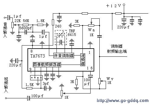
The circuit design philosophy allows for debugging without any RF instruments. Although its performance may not match that of professional equipment, it should be adequate for hobbyists, with audio-visual transmission effects comparable to general-purpose machines. The transmitter consists of...
This schematic is provided with the intention of being useful, but it comes without any warranty, including implied warranties of merchantability or fitness for a particular purpose. The address bus in this schematic is connected in a unique manner,...

A charged capacitor C3 and a momentary pushbutton switch S2 are utilized to temporarily activate relay RE2. The battery being charged powers the relay to maintain its closed state. Additionally, S2 can energize the relay even if the battery...

Automatic antenna switching or RF power indication can be achieved with this circuit. Relay will key with less than 150 mW drive on 2 m. The circuit designed for automatic antenna switching or RF power indication utilizes a relay that...

This relay driver enhances the input impedance using a standard BC547 NPN transistor (or its equivalent). It is a widely used driver capable of operating various relays, including reed relays. Transistors Q1 and Q2 function as a simple common-emitter...
Some time ago, a 1-key keyboard project was developed. The ATTiny microcontroller has been a recurring consideration since then. The 1-key keyboard project utilizes the ATTiny microcontroller, a compact and efficient device suitable for a variety of embedded systems applications....
Warning: include(partials/cookie-banner.php): Failed to open stream: Permission denied in /var/www/html/nextgr/view-circuit.php on line 713
Warning: include(): Failed opening 'partials/cookie-banner.php' for inclusion (include_path='.:/usr/share/php') in /var/www/html/nextgr/view-circuit.php on line 713