
Auxiliary Negative Dc Supply

The circuit employs the CD4009 integrated circuit, which is a hex inverter capable of generating square-wave signals. The frequency of oscillation is dictated by the values of C1 and R1, which create an RC timing network. The oscillation frequency can be adjusted by changing the capacitance of C1 or the resistance of R1, allowing for flexibility in applications requiring different frequencies.
The output from the oscillator is then processed by a rectifying stage formed by C2, D1, D2, and C3. The diodes D1 and D2 are configured to rectify the AC signal generated by the oscillator into a pulsating DC signal. Capacitor C2 acts as a filter capacitor, smoothing the output to reduce ripple voltage, while capacitor C3 may serve as an additional filtering stage to stabilize the output voltage.
The resulting output voltage from this circuit is approximately -3.5 Vdc, which can be utilized in various electronic applications that necessitate a negative voltage supply, such as biasing for certain types of transistors or operational amplifiers. This circuit is particularly useful in scenarios where only positive DC voltages are available, providing a simple and efficient solution for generating a negative voltage supply. In this circuit, IC1 (CD4009) is used as a square-wave oscillator at approx imately 25 kHz. CI and Rl set this frequency. C2, Dl, D2, and C3 form a p-p rectifier, which outputs about -3.5 Vdc. This circuit should be useful where a small negative dc supply is required, but only positive dc voltages are available. 🔗 External reference
Related Circuits
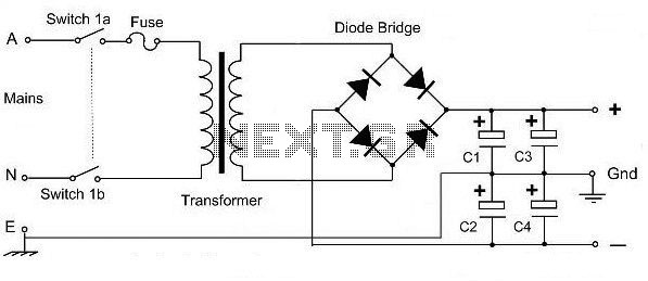
This is a basic dual polarity power supply circuit diagram. It requires the following components: a center-tapped transformer, four diode rectifiers (or one diode bridge), and four electrolytic capacitors. The value of each component is essential for the circuit's...
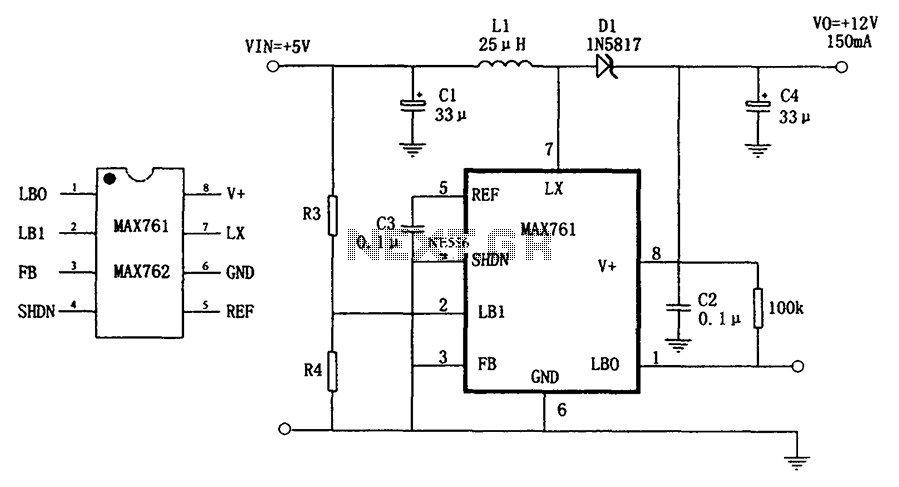
The circuit depicted in the figure illustrates an efficient, low-power step-up DC-DC converter, the MAX761, along with a few external components, which functions as a +5V to +12V boost power supply. Its characteristics include a conversion efficiency of 86%...
A Variable DC Power Supply is an essential tool for electronics hobbyists. This circuit, while not entirely new, is designed to be simple, reliable, robust, and short-proof. It offers variable voltage up to 24V and variable current limiting up...
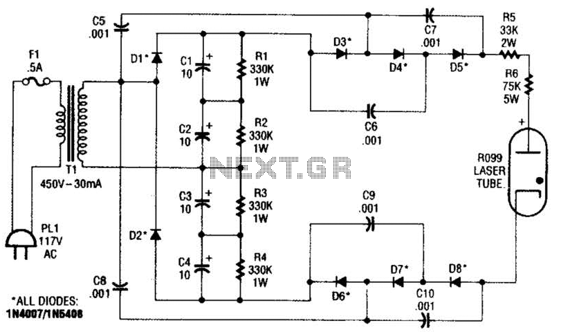
This supply generates an initial high voltage for ignition purposes. After ignition, the supply generates about 1300 to 1500 V. If a higher ignition voltage (than the 6000 V supplied) is necessary, more multiplier stages can be added to...
The circuit is based on application of National Semiconductor. First is constituted by three voltage regulators LM338 [IC1-2-3] connected in parallel. The each one regulator has the possibility of giving 5 A in his output. Also exists the possibility...
This circuit illustrates the power supply wiring diagram for the Nissan 300ZX, a sports car known as the Fairlady Z. Components include the lighting switch, ECCS, and fuse. The power supply wiring diagram for the Nissan 300ZX is essential for...
Warning: include(partials/cookie-banner.php): Failed to open stream: Permission denied in /var/www/html/nextgr/view-circuit.php on line 713
Warning: include(): Failed opening 'partials/cookie-banner.php' for inclusion (include_path='.:/usr/share/php') in /var/www/html/nextgr/view-circuit.php on line 713