
Power Supply Wiring Diagram For Nissan 300ZX
The power supply wiring diagram for the Nissan 300ZX is essential for understanding the electrical system of this sports car. The circuit includes several key components that work together to ensure proper functionality.
The lighting switch is responsible for controlling the vehicle's exterior and interior lighting systems. It connects to the fuse box, which protects the circuit from overcurrent by interrupting the flow of electricity in the event of a fault. The fuse rating should be selected based on the current requirements of the lighting system to prevent damage to the wiring and components.
The ECCS (Electronic Concentrated Control System) is a critical component of the vehicle's engine management system. It regulates fuel injection and ignition timing, ensuring optimal engine performance and efficiency. The wiring from the battery connects to the ECCS, providing the necessary power for its operation. Proper grounding and connections are essential for the ECCS to function correctly, as any interruption in power can lead to engine performance issues.
In summary, the power supply wiring diagram for the Nissan 300ZX encompasses vital components such as the lighting switch, ECCS, and fuse. Each component plays a significant role in the overall electrical system, and understanding their interconnections is crucial for troubleshooting and maintenance.This following circuit shows anpower supply wiring diagram for Nissan 300ZX, sport car called as Fairlady Z. Component: lighting switch,ECCS, fuse .. 🔗 External reference
Related Circuits
This circuit illustrates a 2W RF amplifier based on the M/A-Com LF2810A MOSFET. The transistor is rated for 10 watts at 28 volts. The 2W RF amplifier circuit utilizing the M/A-Com LF2810A MOSFET is designed to amplify radio frequency signals...
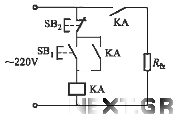
Power outages following a call prevent the re-closure of a circuit, which can help avoid the use of electrical appliances after the power grid is restored. If appliances are left on and a call occurs, it may lead to...
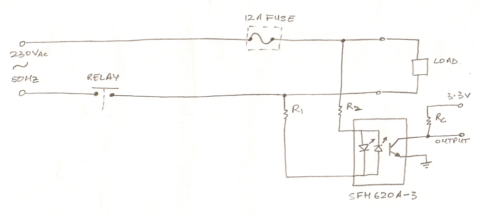
The circuit utilizes an optocoupler (MOC3021) to detect the On/Off state of an electrical appliance using a microcontroller (ATmega16L). The mains supply specifications are 230V, 50Hz. The design aims to determine whether the load is active or inactive. The...
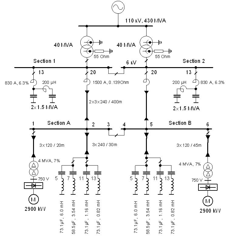
The vertical line indicates the instance of the 5th harmonic filter connection. The diagram illustrates the power system with the designed group of single-tuned filters for a system with a DC drive supplied by a 6-pulse controlled rectifier: PN...
A simplified block diagram of the MiniLOGGER is presented. The CMOS analog multiplexer, 4051, provides output for an 8-channel single-ended input to the analog-to-digital converter chip, CA3162, which operates in free-running mode. The digital output is a 4-bit BCD...
This circuit is a simple form of the commercial UPS, the circuit provides a constant regulated 5 Volt output and an unregulated 12 Volt supply. In the event of electrical supply line failure the battery takes over, with no...