
Basic Dual Polarity Power Supply
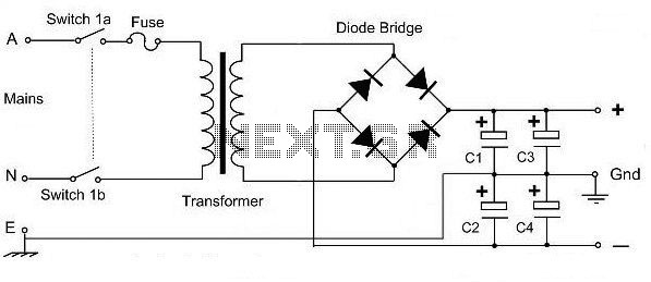
The dual polarity power supply circuit is designed to provide both positive and negative voltage outputs from a single transformer. The center-tapped transformer is the key component, featuring a primary winding connected to the AC mains and two equal secondary windings that produce two outputs, typically referred to as the positive and negative voltages.
The circuit utilizes four diodes arranged in a full-wave rectifier configuration. This setup can also be replaced by a single diode bridge rectifier, which simplifies the design by integrating the four diodes into one component. The rectification process converts the alternating current (AC) from the transformer into direct current (DC), producing both positive and negative voltages relative to the center tap.
Following the rectification, four electrolytic capacitors are employed to smooth the output voltage. These capacitors store charge and help reduce voltage ripple, ensuring a more stable DC output. The values of the capacitors should be selected based on the load requirements and the desired level of ripple voltage. Typically, larger capacitance values lead to lower ripple, but they also affect the response time of the power supply under load changes.
Overall, this dual polarity power supply circuit is fundamental in various electronic applications, including operational amplifiers, analog signal processing, and other devices that require dual voltage supplies. Proper selection of each component, including the transformer ratings, diode specifications, and capacitor values, is critical to the successful implementation of this circuit.This is a very basic dual polarity power supply circuit diagram. It just need the following components: - A Center Tapped Transformer - Diode rectifier 4 units (or diode bridge 1 unit) - Electrolityc capacitor 4 units The value of each comp.. 🔗 External reference
Related Circuits
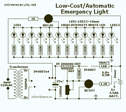
The circuit comprises two sections: charger power supply and LED driver. The charger power supply section is built around a 3-terminal adjustable regulator (IC1) LM317, while the LED driver section is built around transistor BD140 (T2). In the charger...
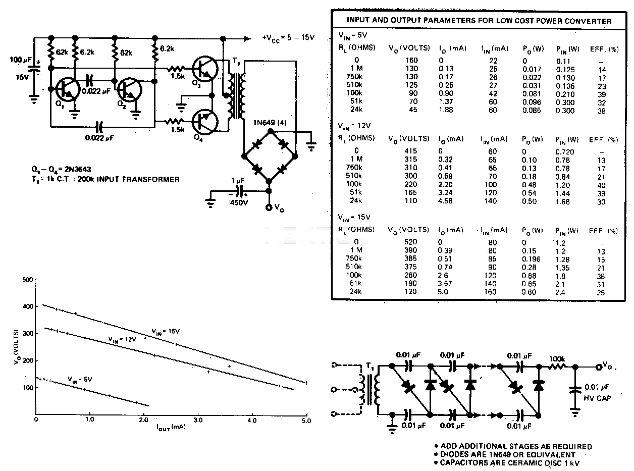
This circuit consists of an astable multivibrator driving a push-pull pair of transistors into the transformer primary. The multivibrator frequency should equal around 1 or 2 kHz. For higher DC voltages, voltage multipliers on the secondary circuit have been...

This document presents a basic electronics project focused on creating a regulated power supply. A regulated power supply is essential for various electronic circuits, as it provides a constant voltage necessary for their operation. Understanding how to construct a...
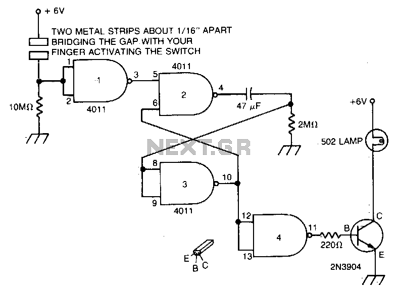
Touch the plate, and the light will turn on and remain on due to the 47 µF capacitor and the 2MΩ resistor for a duration determined by the timing resistor. The circuit described involves a touch-sensitive plate that activates a...
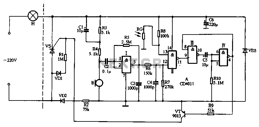
The circuit utilizes CD4011 digital circuits to create a sound-activated light lamp with a dual-control delay section. The left portion of the circuit represents the lighting lines, while the right part consists of the sound and light control delay...
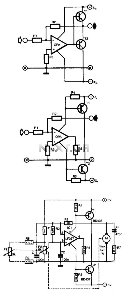
Frequently, the output current of an operational amplifier is inadequate for applications such as driving a small motor or loudspeaker. This issue is typically resolved by adding an emitter follower to the circuit. However, this configuration does not allow...