
AVC Automatic Volume Control Circuit
The automatic volume control (AVC) circuit is a sophisticated device designed to enhance audio signal management in various audio playback systems. This circuit effectively maintains a consistent volume level by dynamically adjusting the gain based on the input signal's amplitude. The FET (T1) is a critical component in this design, acting as a variable resistor that modulates the signal path based on the control voltage applied to its gate. The configuration allows for a broad range of resistance values, which is essential for fine-tuning the circuit’s response to varying signal levels.
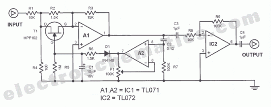
Operational amplifiers A1 and A2 play pivotal roles in the signal processing chain. A1 amplifies the input signal, while A2 further boosts the signal before it is rectified. The gain control provided by potentiometer P1 allows for user adjustments, catering to different audio environments and preferences. The rectification of the negative portion of the output signal from A2 ensures that only the necessary adjustments to T1 are made, contributing to the overall stability of the volume control.
The design incorporates strategic delays through resistors R6 and the discharge characteristics of C1 to ensure that the AVC circuit reacts smoothly to changes in signal amplitude. This prevents abrupt volume changes that could be jarring to listeners. The voltage divider formed by R1 and R4 is critical for managing the input signal level, ensuring that the circuit operates within its optimal range and minimizes distortion.
The inclusion of a high-pass filter with C2 and R7 is a vital feature that allows the circuit to ignore low-frequency signals, which can often lead to undesirable fluctuations in volume control. By adjusting the values of these components, the cutoff frequency can be customized, offering flexibility for various audio applications.
In summary, the automatic volume control circuit is an essential tool for maintaining audio fidelity and listener comfort across a range of devices, from cassette recorders to modern amplifiers. Its ability to dynamically adjust gain while minimizing distortion and managing signal integrity makes it a valuable component in audio engineering.The function of this automatic volume control circuit is to amplify signals without distorting its dynamic compression. The amplitude differences in the signal are levelled off and the disturbing effect vanish. With this tehnique, overcompensation in the volume is avoided. The circuit is used to automatically control the volume levels of cassette recorders, audio tape recorders, amplifiers or radio devices. The AVC circuit works this way: the FET (t1) is used as a variable resistor. The resistance between the drain and source of T1 can be between 150 © and infinite. It is parallel resistor to R2 and togheter with R3 controls the gain of OP amp A1 (around 20 dB). The following OP amp A2 is wired as an amplifier with P1 as its gain control. The negative part of the output signal coming from A2 is rectified and fed to the gate of T1. Small variations on the signal amplitude does not influence the amplification since the FET has a short delay caused by R6. The opposite effect is also slow because of the discharge time of C1. Both effects result to a smooth regulation of the signal amplitude, making this automatic volume control circuit so effective.
The signal voltage at the gate of T1 must be as low as possible to influence the drain-source resistance. To achieve this, the voltage divider R1, R4 is set at the input line to attenuate the signal by 40 dB.
This tehnique enables signals up to 1 Veff to be processed without a problem and with distorsions level below 0. 5%. The signal-noise ratio is over 70dB by an input voltage of 1Veff. The losses at the attenuator is compensated by the amplification through Ai and IC2. The high pass filter made of C2, R7 prevents the bass signals from influencing the regulation. With proper dimensioning of these components, the cutoff frequency of this filter can be adapted to individual needs.
Signals below the threshold set by P1 are amplified by around 18dB. 🔗 External reference
Related Circuits
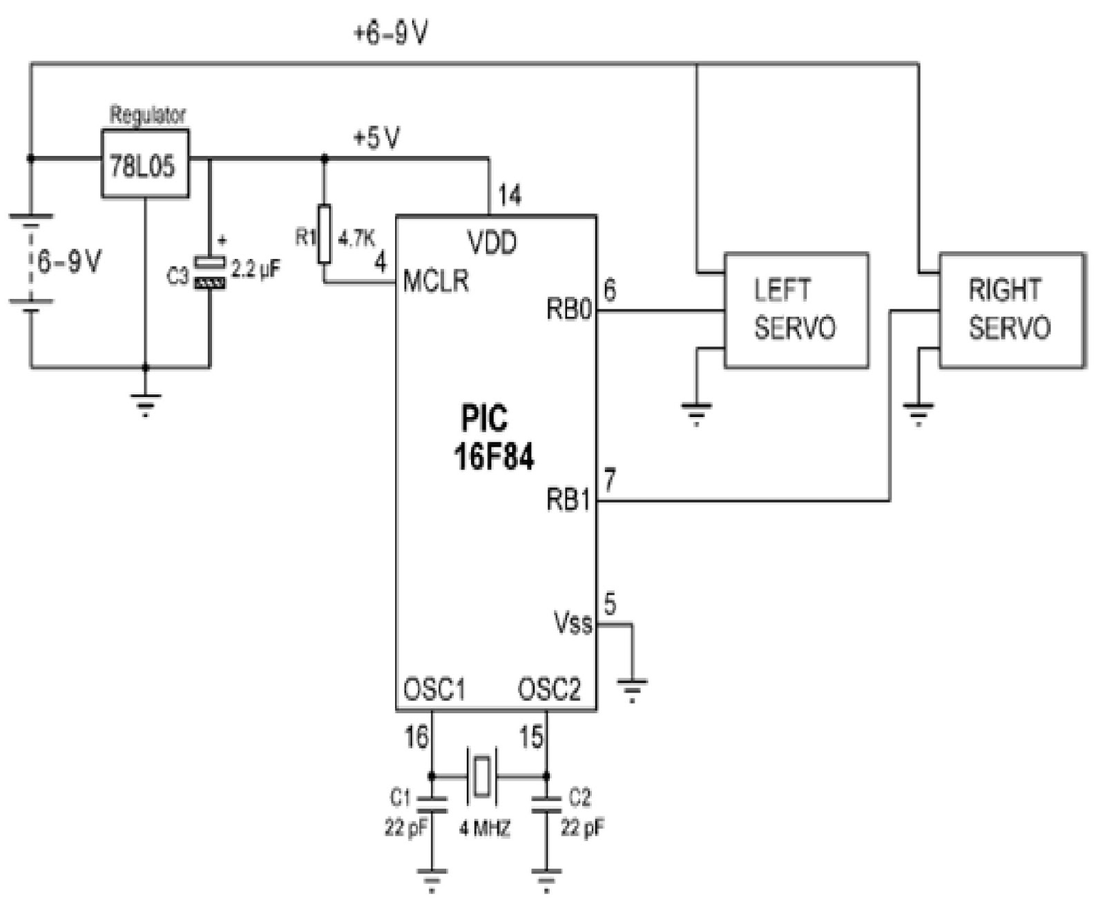
Mobile robots are utilized in various industrial, commercial, research, and hobby applications. This project focuses on controlling a mobile robot using servomotors. The robot is based on a well-known mobile robot called Boe Bot, developed by Parallax. The basic...
This document outlines a battery monitoring circuit designed to measure the voltage of 12V lead-acid batteries, such as those used in automobiles. The circuit utilizes the LM3914 integrated circuit (IC) along with several external components, including a series of...
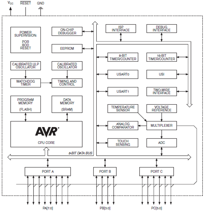
The ATtiny1634 8-Bit AVR Microcontroller from Atmel is based on the enhanced RISC architecture of AVR. It can execute powerful instructions in a single clock cycle, achieving throughputs close to 1 MIPS per MHz. This allows system designers to...
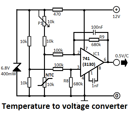
This simple temperature-to-voltage converter circuit allows for precise measurement of room temperature using an NTC resistor or thermistor. The temperature-to-voltage converter circuit typically employs a negative temperature coefficient (NTC) thermistor, which exhibits a decrease in resistance as temperature increases. This...
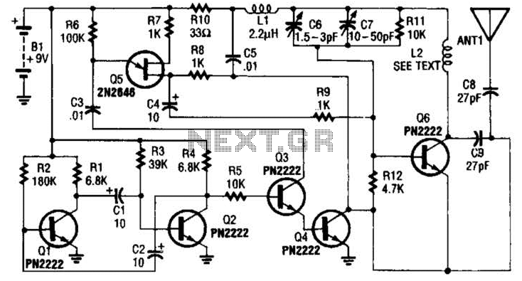
The transmitter utilizes a 6BW6 vacuum tube to achieve an output power of approximately 5 watts. The circuit includes a component CI that is calibrated to produce the cleanest continuous wave (CW) note. The tuning capacitors C8 and C9...
A dimmer is a simple device used to reduce the brightness of incandescent lamps and to control the speed of collector motors. This concept has gained popularity due to the abundance of outdated Soviet circuits available on Lithuanian internet...
Warning: include(partials/cookie-banner.php): Failed to open stream: Permission denied in /var/www/html/nextgr/view-circuit.php on line 713
Warning: include(): Failed opening 'partials/cookie-banner.php' for inclusion (include_path='.:/usr/share/php') in /var/www/html/nextgr/view-circuit.php on line 713