
Dimmer circuit
More: The circuit typically employs a triac such as the BTB04-600SL (manufactured by ST Semiconductors, rated for 600V and 4A with a trigger current of 10mA) and a diac or trigger diode like the DB3, which activates at approximately 32V. Inductors used in these circuits generally have a value around 3mH, although variations exist, with some designs utilizing a 50uH inductor, T0609MJ, and BR100. It is essential to ensure that the maximum ratings of all components are not exceeded. Additionally, it is possible to find triacs and diacs integrated into a single package; an example includes a silicon device discovered in a vacuum cleaner. For a motor with a power rating of about 1500W, the triac-diac combination should be paired with a small aluminum heat sink (approximately 8 square centimeters in size).
The described dimmer circuit operates by controlling the phase angle of the AC voltage supplied to the load, effectively reducing the power delivered to incandescent lamps and allowing for variable speed control in motors. The triac acts as a switch that turns on and off at specific points in the AC cycle, while the diac provides a triggering mechanism to initiate the conduction of the triac.
When the AC voltage rises to the breakdown voltage of the diac, it conducts and triggers the triac, allowing current to flow through the load until the AC cycle crosses zero, at which point the triac turns off. The inductor plays a critical role in smoothing the current and preventing high-frequency noise, contributing to the stability of the circuit.
In designing this dimmer circuit, careful attention must be paid to the component ratings, ensuring that the triac can handle the maximum load current and voltage without overheating or failing. Adequate heat dissipation measures, such as the use of heat sinks, are essential to maintain the reliability and longevity of the components.
Overall, while the circuit may appear simple, the underlying principles of phase control and component selection are crucial for achieving the desired performance and efficiency in dimming applications.Dimmer, from the word n. dim, v. to dim . Simple device to make light of incandescence lamps lower. Also, used to slow down colector motors. All this started because Lithuanian internet is full of old soviet circuits with archaic components. Meanwhile other world is using much better way to dim lamps. Component selection is not very critical: triak BTB04-600SL (ST semiconductors, 600V, 4A, trigger curent 10mA), diak or trigger diode- DB3 ( fire at 32V), inductors was about 3mH. There are lots of versions of this circuit in the internet. In one version I saw 50uH inductor, T0609MJ and BR100. Just check if maximum allowed values are not outmeasured. Also, it is posible to find triak and diak in one package. I found one packade silicon device in some vacuum cleaner. As power of motor was about 1500W, triak-diak was with small aluminium cooler (~8 square centimeters).
🔗 External reference
Related Circuits
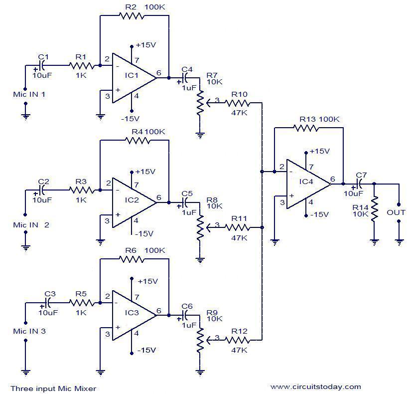
This document outlines a simple three-input microphone mixer circuit utilizing the widely used uA741 integrated circuits (ICs). Four uA741 ICs are employed in this design. IC1, IC2, and IC3 function as preamplifiers, each providing a gain of approximately 40...
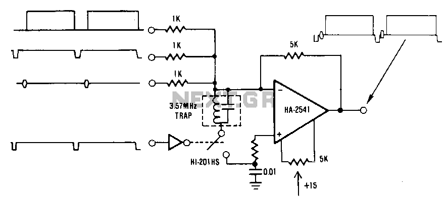
This circuit is a conventional summing amplifier configuration that incorporates a de-clamping circuit. The operation is straightforward; each component—synchronization, color burst, picture information, etc.—of the composite video signal is connected to its respective input terminal of the amplifier. These...

The circuit employs a field-effect transistor (FET) at the input of a Schmitt trigger, allowing the use of a low-value capacitor. The trigger, controlled by Q1 and O2, exhibits a hysteresis of approximately 3V, regulated by a 3V zener...
A video showcases a friend, James, playing his electric guitar, connected through an audio echo effect system to an amplifier. The echo effect is implemented on a breadboard rather than through hidden pedals or amp options. Apologies are made...

A simple battery charger circuit with reverse polarity indication is presented. The circuit utilizes the L200 integrated circuit, which is a five-pin variable voltage regulator. It can be powered by DC voltage from either a bridge rectifier or a...
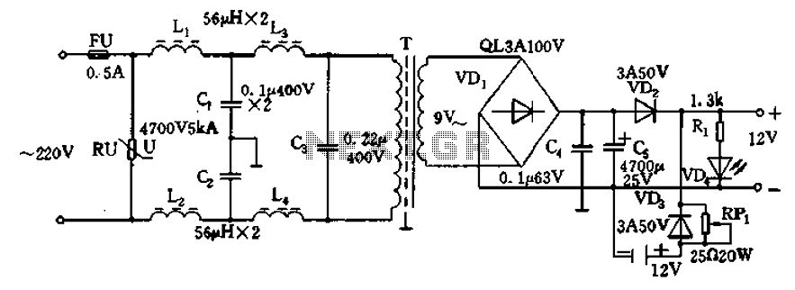
12V DC power supply circuit. A typical 12V DC power supply circuit includes a transformer that converts mains voltage to the required 12V AC output. It features a full-wave rectifier and a capacitor filter. The circuit typically incorporates a...
Warning: include(partials/cookie-banner.php): Failed to open stream: Permission denied in /var/www/html/nextgr/view-circuit.php on line 713
Warning: include(): Failed opening 'partials/cookie-banner.php' for inclusion (include_path='.:/usr/share/php') in /var/www/html/nextgr/view-circuit.php on line 713