
battery monitor circuit
The battery monitor circuit serves as an effective solution for continuously monitoring the voltage levels of 12V lead-acid batteries, providing a visual representation through the use of LEDs. The LM3914 IC is a voltage level indicator that can drive multiple LEDs in a bar graph or dot mode, making it suitable for applications requiring voltage visualization.
In this configuration, the circuit is designed to accommodate a voltage range that corresponds to the typical operating levels of 12V lead-acid batteries. The use of a digital voltmeter during setup is crucial for precise calibration. By connecting the voltmeter to the designated pins of the LM3914, the user can ensure that the voltage reference is accurately set to 1.2 volts, establishing a baseline for the LED indicators.
The variable resistors VR1 and VR3 are used to fine-tune the sensitivity and response of the circuit. Setting these resistors to their center positions allows for a balanced calibration, ensuring that the LED indicators respond appropriately across the desired voltage range. The span adjustment of VR1 to equal 4.5 volts is essential for ensuring that the full scale of the LED indicators corresponds accurately to the voltage levels being monitored.
The resulting circuit can provide real-time feedback on the state of the battery, alerting users to potential issues such as over-discharge or under-voltage conditions, which can be detrimental to lead-acid batteries. This monitoring solution is particularly useful in automotive applications, where maintaining battery health is critical for vehicle performance and reliability. Additionally, the circuit can be adapted for use in other applications requiring similar voltage monitoring, making it a versatile tool for electronics engineers and hobbyists alike.Here is a battery monitor circuit which can be used to monitor the voltage of 12V lead acid batteries such as car batteries. The circuit is built around the LM3914 IC and some external components with 10 LEDs which will indicate the voltage level.
Two equipment are required for adjusting the circuit for 12 volt battery, one is lab power supply and second is digital volt meter. First you have to connect the digital volt meter to the pin 4 and pin 6 of the IC and adjust the variable resistor VR2 for a reading of 1. 2 volts and make VR1 and VR3 on their center settings now if the span between VR1 ends equal to 4. 5V then the circuit is ready to use. 🔗 External reference
Related Circuits
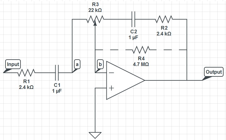
This circuit can function as a treble control circuit, with high-frequency gain occurring when resistor R3 is set to a value that makes points a and b equal (denoted as k=0). Conversely, high-frequency attenuation occurs when R3 is set...

This device offers numerous implementation possibilities due to its wide input voltage range and large maximum output current across a broad output voltage spectrum. It features long battery life and low power consumption owing to its high efficiency and...

A crystal oscillator operates at a frequency of 51 MHz, which corresponds to the third harmonic of a 17 MHz fundamental frequency. Depending on the specific structure used, the drain-gate capacitance can be selected within a range of 0.5...

This is a wideband high-frequency amplifier circuit designed for a frequency range between 75-150 MHz. It utilizes a PNP transistor amplifier to enhance signal strength before it reaches the receiver of devices such as phones, FM radios, or amateur...

When this car alarm circuit is activated, it remains active for 80 seconds. There is a 15-second delay for the driver to enter and deactivate the alarm. All timings can be easily modified. The circuit utilizes two NE555 timers,...
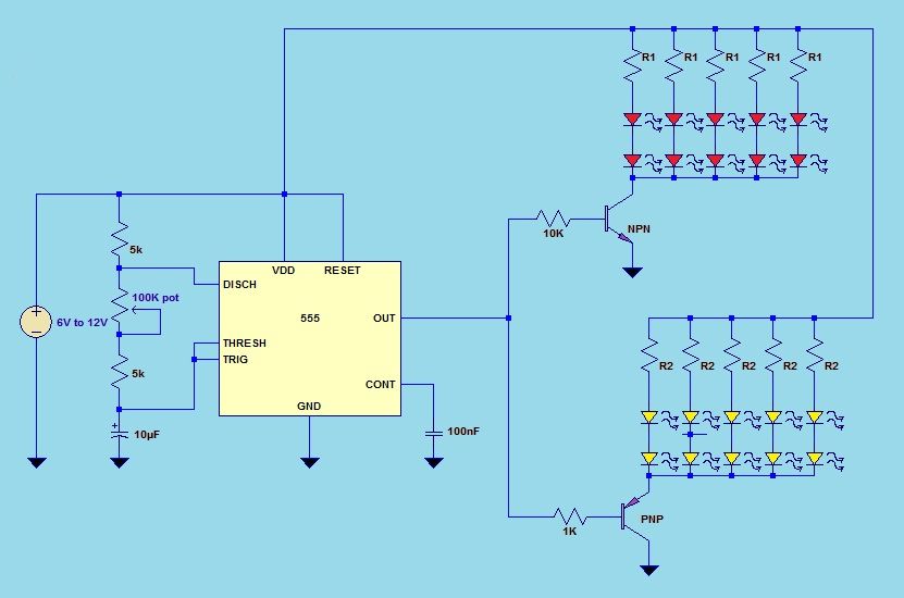
This project utilizes a 555 timer integrated circuit (IC) in an 8-pin configuration to control multiple LEDs. It is designed for quick assembly and allows for the adjustment of timing functions. The circuit employs a 555 timer in astable mode,...