
AVR
The line follower robot system relies heavily on its sensor array to navigate effectively along designated paths. The integration of various sensors allows for adaptability to different track conditions, whether they are bright, dark, or patterned. The operational amplifier, functioning as a comparator, plays a crucial role in converting the analog signals from the sensors into digital signals that the microcontroller can process. By adjusting the reference voltage through resistor R9, the sensitivity of the sensors can be tailored to respond optimally to the specific lighting conditions and track colors present in the environment.
The configuration of the sensors can vary depending on the complexity of the robot's intended tasks. For basic applications, a simple arrangement of two photo diodes and corresponding LEDs may suffice. However, for more advanced navigation, additional sensors can be added to increase the robot's responsiveness and accuracy. The use of cameras as image sensors introduces a sophisticated layer of functionality, enabling the robot to interpret more complex visual data and make informed decisions based on the surrounding environment.
In designing the circuit, careful consideration must be given to the power supply and grounding to minimize noise and ensure stable operation. The placement of the sensors on the robot's chassis is also critical; they must be positioned to maintain consistent contact with the ground while avoiding obstructions that could interfere with their readings. The overall performance of the line follower robot is a culmination of these design choices, sensor configurations, and the effective integration of the microcontroller with the sensor output.The article "Creating a Line Follower Robot with AVR [Censorship]" is a continuation of Line Follower Robot article with a new AVR ATMega8535 samapai phase Li ne Follower Robot block diagram. In the article "Creating a Line Follower Robot with AVR Part 1 [Sensor]" This is a review of the sensor used on Line Follower Robot, and the components used. Sensors, can be analogous to the `eye` of a robot that serves to `read` the black line of the track robot or vice versa.
So that the robot is able to know when he will turn right, when he turned left and when he stopped. Sensors used are usually photo reflector, LDR (Light Dependent Resistor), Photo Diodes and Photo Transistor - mounted on the front two or more below the line follower robot. There also are using the camera as a sensor (or image sensor) to a higher-resolution readout line, making more accurate robot motion.
The working principle of the sensor is simple, when the transmitter (infrared) emitting light onto a white field, the light will be reflected back to the receiver by the white areas and vice versa. This gives the change in the voltage level at the receiver output, but it usually changes the voltage can not be accepted as a TTL logic level.
To be able to read by the microcontroller, the sensor voltage should be adjusted to TTL voltage level that is 0-1 volts for logic 0 and 3-5 volts for logic 1. This can be done by installing the operational amplifier is used as a comparator as shown in the picture above.
Op Amp is used as a comparator LM324 IC, because IC is able to work at VCC 5 volt range and there are 4 in 1 Op Amp IC corresponding to the number of sensors are used. The sensitivity of this sensor can be set through R9 which controls the comparator reference point. Line follower robot sensors can be made with a combination between LED and photo diode. Line follower robot sensor configuration is good to be able to read the track with a hard and fast. To make the robot sensor is firm and fast can not merely rely on the ability of photo diodes and LED configurations only.
As an alternative to maximize the performance of line follower robot sensors can be added to the voltage comparator with Op-Amp. sensor circuit line follower robot equipped with a voltage comparator that is ready to be connected to a microcontroller or PIC can use the following series of robot sensor.
🔗 External reference
Related Circuits

Works on AVR controllers with RAM and a hardware UART. This code is easily modified to integrate with ROM applications to provide the ability to monitor and interact with ROM applications via a terminal simulation program over an RS-232...
This instrument requires two precision components: A precision capacitor and a precision inductor. You only need to start with one precision component, either the reference capacitor or the reference inductor, and using this meter, you can select or adjust...
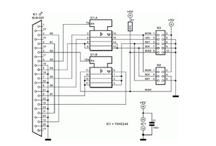
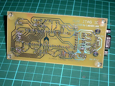
This circuit is designed to program AVR controllers, specifically the AT90S1200, using a parallel port. The circuit is very straightforward. IC1 serves as a buffer. The circuit operates by interfacing the parallel port of a computer with the AVR microcontroller....
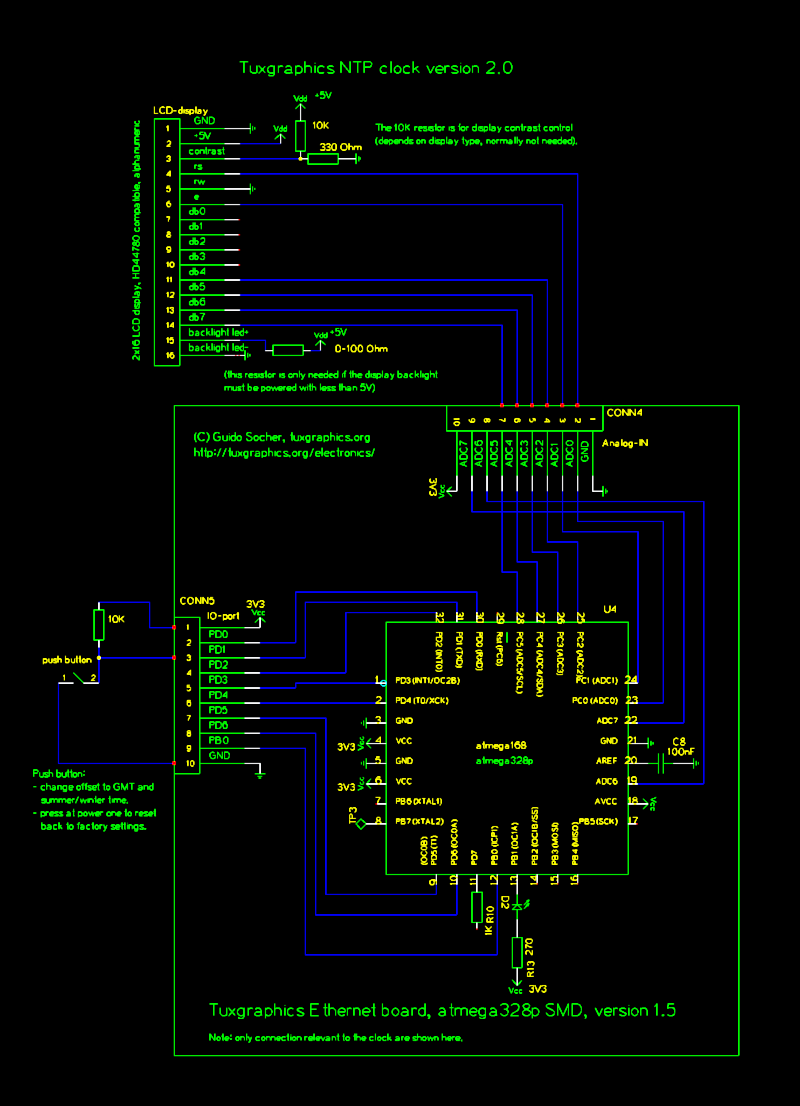
The Network Time Protocol (NTP) has transformed global timekeeping, enabling accurate date and time retrieval from anywhere in the world. NTP is a straightforward UDP-based protocol that can be implemented in microcontrollers. The Tuxgraphics NTP clock has gained popularity...
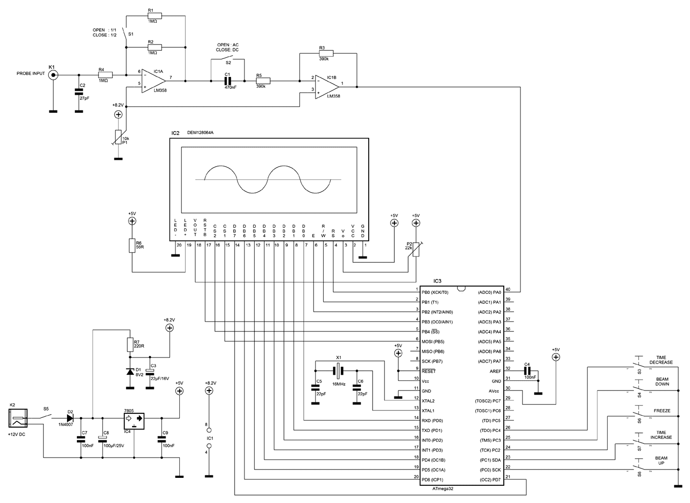
A few months ago as I was surfing on the net, I saw an oscilloscope based on PIC18F2550 microcontroller and a KS0108 controller based graphical LCD. That was Steven Cholewiak's web site. I had never seen before so amazing...
This circuit is designed to program AVR controllers such as the AT90S1200 using a parallel port. The circuit is straightforward, with IC1 serving as a buffer for the signals transmitted between the parallel port and the microcontroller. This encompasses...