
AVR LCD Microcontrolled Oscilloscope
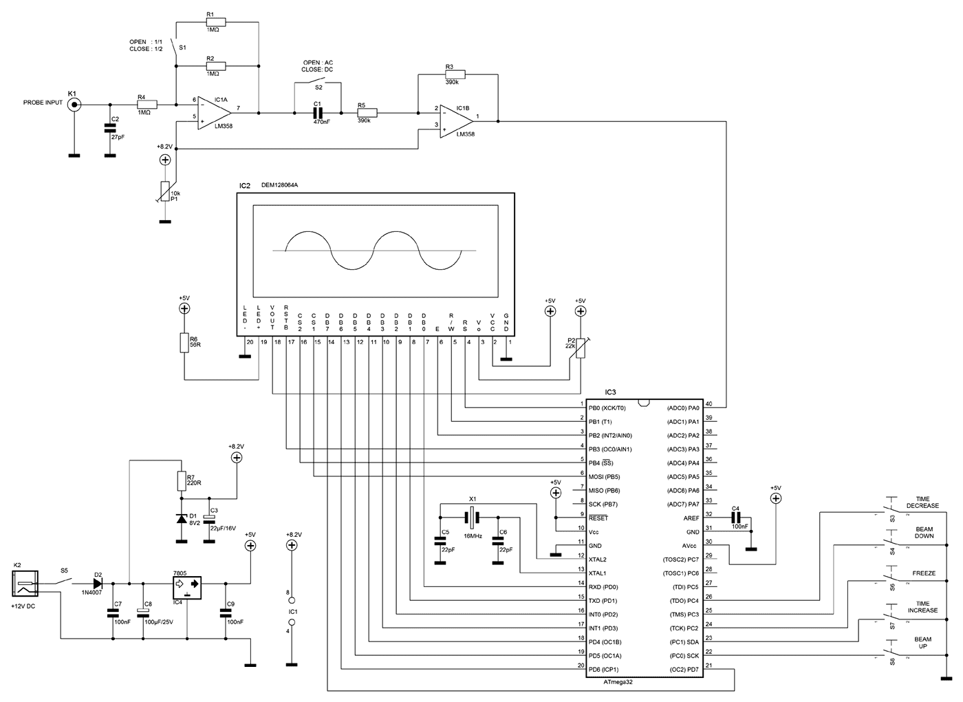
The operating voltage of the circuit is 12V DC. By this voltage, the power supply is producing 2 voltages: +8.2V for IC1 and +5V for IC2 and IC3. This circuit can measure from +2.5V to -2.5V or from 0 to +5V dependent by S1 position (AC or DC input). By using a probe with 1:10 division, it is possible to measure almost 10 times higher voltages. Moreover, with S2, an extra division by 2 of the input voltage can be achieved.
Programming the ATmega32 involves burning the ATmega32 with the AVR_oscilloscope.hex file and selecting an external crystal in the fuses section. It is crucial to disable the JTAG interface from the ATmega32 microcontroller; otherwise, the device will restart at the initial screen when transitioning to the oscilloscope screen.
Calibration of the oscilloscope requires adjustment of two components: the LCD contrast trimmer (P2) and the beam positioning potentiometer (P1). To calibrate, apply power to the circuit, then adjust P2 until the pixels on the screen are clearly visible. Following this, adjust P1 to center the beam on the LCD along the horizontal line of the cross.
Usage of the oscilloscope involves controlling the beam's vertical position using buttons S8 (up) and S4 (down) to measure voltage, with 1 volt corresponding to 1 square height on the display. The measurement speed can be adjusted using S7 (increase speed) and S3 (decrease speed), with a minimum displayable waveform frequency of 460Hz. For lower frequency waveforms, such as 30Hz, the S7 button can be pressed to shrink the waveform or S3 to extend it up to the maximum sampling rate. The oscilloscope features an automatic trigger function, which is effective for continuous signals (e.g., triangle waveforms). For unstable signals (e.g., serial transmission), the screen can be frozen by pressing S6, allowing for a snapshot of the measurement signal, which will end upon releasing the S6 button.A few months ago as I was surfing on the net, I saw an oscilloscope based on PIC18F2550 microcontroller and a KS0108 controller based graphical LCD. That was Steven Cholewiak's web site. I had never seen before so amazing microcontroller-only oscilloscope. That was realy impressive circuit, so I decided to design something like that but in C language instead of assembly that I was using all those years.
The best solution for me was the WinAVR as it bases on open source AVR-GNU compiler and it works perfect with AVR studio 4. The graphics library that I used, is made by me specific for this project. It's not for general use. If you want to include it to your codes, you have to convet it as you need to. The maximum signal speed who can show up this oscilloscope is 5 kHz in square signal. For other signals (sine or triangle) the frequency is lower ( almost 1 kHz) for having clear view of the signal. Description The operating voltage of the circuit is 12V DC. By this voltage, the power supply is producing 2 voltages. +8.2V for IC1 and +5V for IC2 and IC3. This circuit can measure from +2.5V to -2.5V or from 0 to +5V dependent by S1 position (AC or DC input).
By using probe with 1:10 division you can measure almost 10 times higher voltages. Moreover, with S2 you can make an extra division by 2 the input voltage. Programming The ATmega32 Burn the ATmega32 with AVR_oscilloscope.hex and select external crystal at the fuses section. After that, you Must disable the JTAG interface from your ATmega32 microController. If you don't do that, the mega32 will show you the initial screen and when it go to the oscilloscope screen it will restart immediately to the initial screen and it will stay there for ever.
Calibrations The only 2 things you have to calibrate is the LCD contrast trimmer P2 and the P1, to move the beam at the center of the LCD. To do that, apply only the power supply to the circuit and adjust the P2 up to the point you will see clear the appeared pixels on the screen.
Then, adjust the P1 up to the point the beam is moved at the middle of the LCD (at the horizontal line of the cross). Usage You can move the beam up or down the screen by pressing the buttons S8 or S4 correspondingly to measure the voltage of the signal.
1 volt is taking up 1 square height. With S7 and S3 you can increase or decrease the measurement speed. The minimum speed of a waveform that can be displayed on LCD is 460Hz. If you want to view a lower frequency waveform, for example 30 Hz, you can press the S7 to shrink the waveform or S3 to extend the waveform up to the maximum sampling rate. This oscilloscope has an automatic trigger. That means, if you have a continuous signal (ex a triagle waveform) the auto trigger will work perfect.
If your signal is not stable (ex a serial transmittion) you can freeze the screen by pressing S6 switch. At his case you can get a snapshoot of your measurment signal. By the time you release the S6, the snapshoot will end. 🔗 External reference
Related Circuits
If no characters are displayed on the LCD and the hardware and software have been verified as functional, adjust the LCD Contrast potentiometer until the characters become visible. To send an 8-bit character or command to the LCD via...
Martin Ustek has modified the project to include a Sokoban game. Information about his version can be found throughout this page; for full details, please visit his website (Czech). Either game can be selected with a menu that appears...
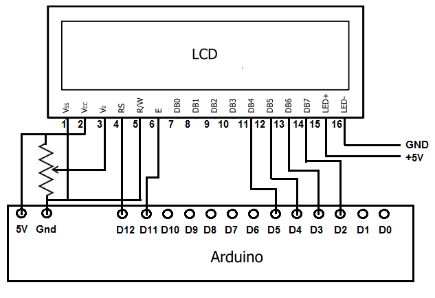
To achieve this, the first step involves establishing the necessary physical connections between the Arduino board and the LCD. Following this, code must be written to display the desired text on the LCD. LCDs have become the standard means...

Bruco Integrated Circuits B.V. - Case: Automotive alternator voltage regulator - Bruco. The automotive alternator voltage regulator designed by Bruco Integrated Circuits B.V. is a critical component in modern vehicle electrical systems. This device is responsible for regulating the voltage...
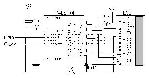
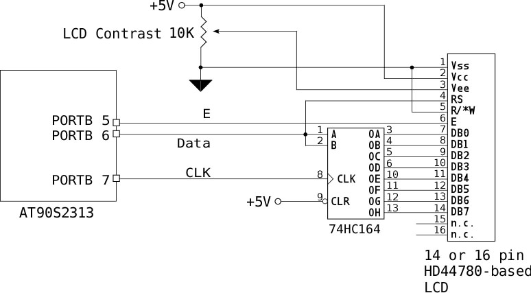
The most popular LCD interface is the Hitachi 44780 based LCD controller chip which provides a fairly easy to work with interface and low power consumption. The major drawback of the interface is the perceived complexity of working with...
An LCD (liquid crystal display) is an electronically modulated optical device composed of multiple pixels filled with liquid crystals, arranged in front of a light source (backlight) or reflector to create images in color or monochrome. The block diagram...