
AVR Dongle
The circuit utilizes a parallel port interface to facilitate communication with the AVR microcontroller, specifically designed for programming tasks. The inclusion of IC1 as a buffer is crucial, as it ensures that the signals from the parallel port are adequately conditioned for the microcontroller's input requirements, thus preventing potential damage from signal levels that are too high or too low. The use of standard ISP pinouts (K2 and K3) aligns with industry practices, allowing for compatibility with a wide range of AVR development boards and tools. This design choice not only enhances usability but also promotes a modular approach to microcontroller programming.
The programming software, ATMEL AVR ISP, is essential for executing the programming sequence. It communicates with the microcontroller through the buffered signals, allowing for the transfer of firmware or configuration data. Users are encouraged to download this software to facilitate the programming process effectively.
For construction, the circuit is intended to be assembled on a standard prototype board. This approach allows for flexibility in layout and component placement, accommodating various configurations. The simplicity of the design, characterized by a minimal number of components, aids in reducing assembly errors. It is recommended that builders, particularly those with limited experience, follow a systematic approach by marking off connections on the schematic as they are completed. This method not only aids in ensuring accuracy but also serves as a valuable learning tool for understanding circuit assembly and troubleshooting. Overall, this circuit serves as an accessible introduction to programming AVR controllers, making it suitable for both novice and experienced users.This circuit is intended to program AVR controllers such as the AT90S1200 via the parallel port. The circuit is extremely simple. IC1 provides buffering for the signals that travel from the parallel port to the microcontroller and vice versa. This is essentially everything that can be said about the circuit. The two boxheaders (K2 and K3) have the standard` ISP (in system programming) pinout for the AVR controllers. The manufacturer recommends these two pinouts in an attempt to create a kind of standard for the in-circuit programming of AVR-controllers. These connections can be found on many development boards for these controllers. The software carries out the actual programming task. It is therefore necessary to have a program (ATMEL AVR ISP), which is available as a free download from The construction of the circuit will have to made on standard prototype board, since we didn`t design a PCB for this circuit.
This should not present any difficulties considering the small number of parts involved. We recommend that inexperienced buildersrst make a copy of the circuit and cross off each connection on the schematic once it has been made on the board. This makes it easy to check after-wards whether all connections have been made or not. 🔗 External reference
Related Circuits
Currently, USB is the most widely used connection between PCs and peripherals, such as AVR programmers, printers, and scanners. Therefore, it became necessary to modify an old serial AVR In-System Programmer (ISP) to function with a USB connection. One...
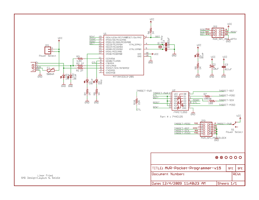
At the bottom, there is a 74AC125, which is a quad buffer with tri-state outputs. Numerous buffers of this type have been observed in programmers. The function of these buffers is not entirely clear, but it is assumed that...
A bicycle light control circuit that reads various buttons and sets multiple outputs such as headlights, taillights, and blinkers. The design utilizes an ATtiny24 microcontroller, operating at an internal oscillator frequency of 8 MHz, and is programmed in C...
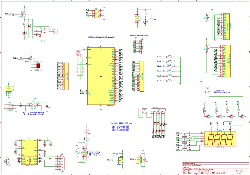
A circuit diagram was created using KiCad, which is considered an excellent free software for designing electronic diagrams and printed circuit boards. KiCad is a powerful open-source software suite that allows engineers and hobbyists to design electronic circuits and...
.jpg)
This project is a combined temperature and humidity meter. It is an enhancement of a previous PIC-based humidity meter and PIC and AVR thermometers. The design utilizes an ATmega164 microcontroller, which offers ample input/output ports and memory. The humidity...
This is a design for a frequency meter based on AVR microcontrollers. Maximum input frequency is specified to be 30 MHz in the multi-chip configuration, and in single-chip configuration, there are both 5 MHz and 10 MHz versions operating...