
AVR Color Clock
The circuit design for the color clock is centered around the ATMEGA88 microcontroller, which serves as the brain of the system. The microcontroller interfaces with two RGB LEDs, each assigned to represent hours and minutes respectively. The choice of RGB LEDs allows for a broad spectrum of colors to be utilized, enhancing visibility and aiding those with visual impairments.
The circuit employs a straightforward current-limiting approach, utilizing 220-ohm resistors for each LED. This ensures that the LEDs operate within their safe current ratings, preventing damage and maintaining consistent color output. The PWM capability of the ATMEGA88 is leveraged to control the brightness and color mixing of the LEDs, allowing for discrete color representation that corresponds with the time displayed.
The DCF receiver module is a critical component, providing accurate time information through radio signals. It connects to an I/O pin on the microcontroller, simplifying the integration process. The software handles the decoding of the DCF signal, ensuring that the clock remains accurate even in varying signal conditions. Additionally, the manual time-setting feature provides flexibility, allowing users to adjust the time easily when the DCF signal is unavailable.
Power management is efficiently handled by a 7805 voltage regulator, ensuring a stable 5V output for the entire circuit. The inclusion of a rectifying diode safeguards against incorrect power supply connections, enhancing the circuit's reliability.
The physical layout of the clock utilizes Plexiglas rods to facilitate light conduction, ensuring that the colors mix effectively for optimal visibility. The experimental board design allows for easy modifications and adjustments during the development phase, while the dual-board setup enhances stability and supports the overall structure.
Overall, the color clock represents a thoughtful integration of technology and user-centric design, making it a practical solution for individuals with visual impairments. The combination of clear visual indicators, reliable timekeeping, and ease of use makes this clock a valuable addition to any environment where accessibility is a priority.This page describes a color clock that displays the time using two RGB LEDs, one for hours and one for minutes, showing time by using the standard color coding used for components (with two additional colors as the standard color coding only has ten colors and twelve is needed). The time could have been shown more analogue by fading the colors but then it would be harder to read as the human color perception is quite bad. With the discrete solution with 12 well defined steps for both hours and minutes it is possible to tell the time with an accuracy of five minutes, and this accuracy is often good enough. The reason I made this clock was that my wife has really bad sight and need strong glasses to read the clock, and putting on the glasses at night just to see the clock at night if she wakes up will really make her awake and make it hard to get back to sleep.
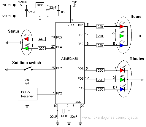
So I made her this clock as my birthday present for her on her 26th birthday (October 2007) to make it possible for her to see what time it is without putting on her glasses. As you can see in the schematic to the right it is a very simple design. The clock is controlled by an ATMEGA88 that drives the two RGB LEDs directly. The RGB LEDs have 220ohm resistors for current limiting, as it turns out the color temperature gets about right when all resistors are the same for the RGB LEDs that I used.
The two RGB LEDs are pulse width modulated by the built-in 6-channel PWM-circuit in the AVR. There is a status RG LED to indicate status of the DCF receiver, this is too driven directly by the AVR using only current limiting resistors (220/440ohms to get yellow when both are lit). The DCF receiver is a module that is just a radio that only outputs the DCF-time code according to the pulse width carrier modulation format that it is sent out from the transmitter in Frankfurt and thus must be decoded in the AVR.
The DCF-receiver is just connected to an IO-pin of the AVR and the rest is taken care of by software. For times when the DCF-signal is not available it is possible to set the time manually using a switch, the switch is very straight-forward too just connected to an IO-pin.
Finally, the power supply is very standard, just using a 7805 to get 5v, and as usual I put a rectifying diode to protect the circuit against wrong polarity. As this was a very simple and quick build, I`ve not made any PCB for it, I`m just using experimental "dotted" board.
This also means that you can`t buy a kit for this project in my webshop, but if there is a large interest for a kit I`ll make a PCB layout and kit for my shop. To get the two color dots separated and to get a longer light conductor to get the colors really mixed (the longer light conductor the better the colors get mixed) I`ve used two Plexiglas rods that I`ve heated up and bent to a nice shape.
The experiment board that the system is built on is divided into two parts, one main board with RGB LEDs, AVR and power supply, and one board with the status RG LED and the switch, the later board is also used to make the light conductors (Plexiglas rods) more stable by reducing the torque where the rods are glued to the box as it gives support on a second place as shown in the sketch here down to the right: The software is very simple, the PWM for the RGB LEDs is taken care of by the AVRs hardware so that only means setting up some timers to get that right, then the PWM-registers are just loaded with the values from a lookup table. Then there is one state machine that handles the three modes of setting minutes, setting hours and just showing the time.
Mode is changed by holding down the switch for a couple of seconds until the LEDs start blinking, and then a short push will change the time (color). The status LED is updated by the status of the time, it will be blinking red according to the received DCF signal when it was more than 72 hours since the last correct time code was receive
🔗 External reference
Related Circuits
The 5 V from USB appears to be powering the LED on the laptop power brick. Therefore, even when the power brick is turned off at the wall outlet, the LED remains illuminated. When the USB is unplugged, the...

This document outlines the construction of a pendulum-controlled clock designed for high accuracy. Although it has a retro appeal, it represents an intriguing project. The project requires a spare quartz clock, which must be modified by isolating two pads...
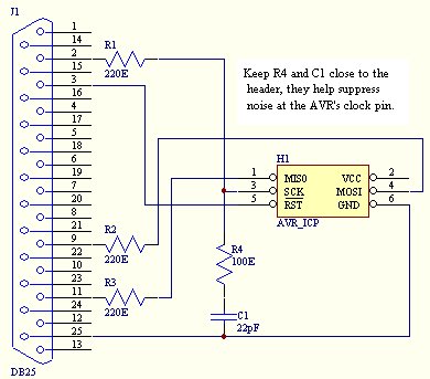
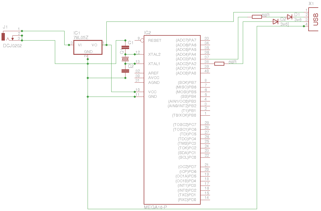
An In Circuit Programmer is a very valuable tool. Not only does it allow you to program your AVR's with ease, you can update your program without having to remove the AVR (very useful when working with surface mount...
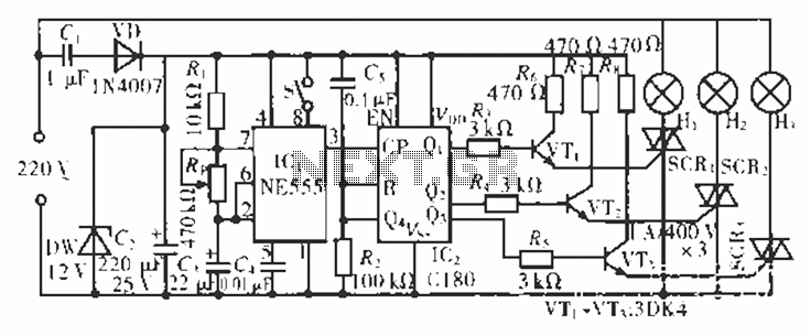
The circuit operates at 220 V AC using a C1 buck converter and a DW regulator. The VD ensures the entire stream is processed, and C2 provides a filtered output of 12 V DC for the voltage supply control...

Abstract Can you recall the movie Entrapment, in which the lead actress, Katherine Zeta-Jones, attempted to bypass the security systems of a building to obtain a highly valuable item? In the film, she had to train extensively to navigate...
The primary advantage of this programmer is its capability to safeguard both the target device and the PC from unexpected voltages when either side is powered down. The buffers utilized are open-drain, with each buffer connected to the Vcc...