
Simplest AVR programmer

An In Circuit Programmer (ICP) facilitates the programming of AVR microcontrollers directly in their working environment, significantly enhancing the development workflow. This device is particularly advantageous for applications involving surface mount devices (SMDs), where physical access to the microcontroller can be limited. The ICP allows firmware updates to be performed without the need to desolder the microcontroller from the PCB, thereby minimizing the risk of damage and reducing development time.
The circuit design typically includes a direct connection from a computer's printer port to the AVR microcontroller. The programming signals are transmitted through this connection, enabling the microcontroller to be programmed and debugged in situ. A reset circuit, composed of a 10KΩ resistor in series with a 100nF capacitor, is often incorporated to ensure that the microcontroller can be reset effectively during programming. This reset circuit stabilizes the programming sequence and ensures that the microcontroller is in the correct state for programming.
While a buffer can be integrated into the circuit to enhance signal integrity between the printer port and the AVR, it is not strictly necessary. The simplicity of the direct connection has been proven effective in numerous applications, demonstrating reliability and performance over extended periods. The versatility of the ICP allows it to support a wide range of AVR microcontrollers, making it a universal tool for developers working with various AVR architectures.
Overall, the In Circuit Programmer is an essential tool for embedded systems development, offering ease of use, flexibility, and efficiency in programming AVR microcontrollers.An In Circuit Programmer is a very valuable tool. Not only does it allow you to program you AVR's with ease, you can update your program without having to remove the AVR (very use full when working with surface mount devices). Also, an ICP allows you to use one tool to program possibly every AVR available today. This circuit functions well even when a reset circuit consisting of a 10K resistor and a 100nF cap is present. The printer port is directly connected to the AVR, a buffer can be added if you want but we've used this circuit for years without any problems.
🔗 External reference
Related Circuits
GTP USB PIC Programmer (Open Source). This project includes the GTP USB (not plus or lite). The schematic, photos, and PCB have been developed by PICMASTERS. The GTP USB PIC Programmer is an open-source device designed for programming PIC microcontrollers...
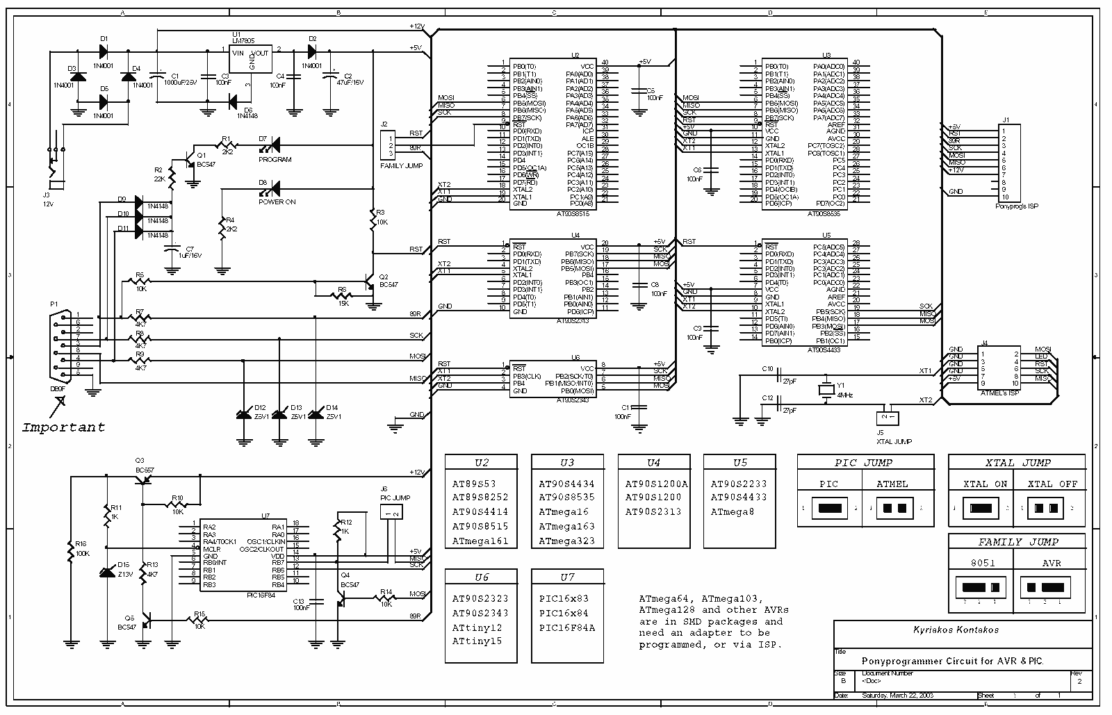
All resistors are 1/4W. The circuit is powered by 9...15V DC or AC. When In Circuit Programming (ISP) connectors are used, it is possible for the programmer to be powered from the target's power source. Diodes D2 and D6...
Most inverters available in the market utilize a modified sine wave to achieve better output at a competitive cost. The modified sine wave unit employs a 50% fixed PWM square wave, with the peaks balanced by a capacitor to...
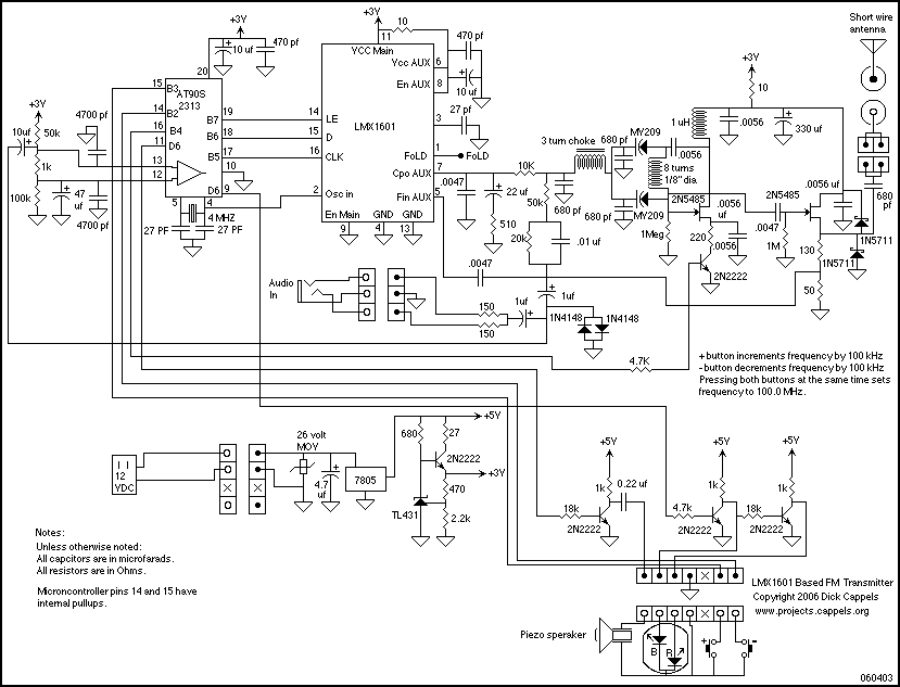
An LMX1601 Phase locked loop, a discreet FET VCO, and an AVR microcontroller combine to make a stable, easy to use monophonic FM transmitter that includes an audio activated switch that turns the transmitter on only when it is...
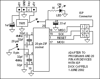
This adaptor lets me program 8 or 20 pin DIP devices using the In-System Programmer (ISP) described in Atmel's AVR910 application note. This circuit provides power and clocks for the part to be programmed and power to the ISP...
When first encountering this article, it is apparent that it presents an excellent project utilizing only a few components. Microcontroller projects based on LEDs are particularly appealing. This project involves the design and implementation of a microcontroller-based LED circuit, which...