
mosfet AVR Pin Dual Use: Input and Output at (seemingly) the same time
The bicycle light control circuit leverages the ATtiny24 microcontroller to manage multiple output states based on user input through buttons. The internal oscillator, operating at 8 MHz, facilitates efficient processing of PWM signals and ADC readings. The circuit's architecture is designed to minimize external component usage, particularly avoiding complex shift registers while utilizing inexpensive resistors for biasing and current limiting.
The MOSFETs (NTD4960N) are employed to manage high current loads from the LED banks, which are configured in parallel strings. Each string consists of three white LEDs in series, with a forward voltage drop of approximately 3.3V. The design allows for a total LED current of about 2A, ensuring adequate brightness for both safety and visibility during night rides.
The PWM control strategy is crucial for managing LED brightness, with a frequency of 200 Hz and a maximum duty cycle of 90%. This approach not only enhances the visibility of the bicycle lights but also conserves battery life by reducing average power consumption. The circuit intelligently switches the output pin to input mode during the last 10% of the PWM cycle to read the state of the buttons without affecting the MOSFET operation.
The ADC is configured to read the button states, utilizing the internal 1.1V reference for accurate readings. The design ensures that even when a button is pressed, the voltage at the MOSFET gate remains below the threshold required for conduction, effectively keeping the LEDs off. This feature is critical for maintaining control over the light outputs and preventing unintended illumination.
The interrupt-driven design allows for responsive button handling, with the main program processing button states based on readings collected during the PWM cycles. The careful timing and management of ADC readings ensure that the circuit operates smoothly, providing reliable performance in various lighting conditions.
Overall, this bicycle light control circuit represents a sophisticated integration of microcontroller technology with practical electronic design principles, aimed at enhancing safety for cyclists through effective lighting solutions.A bicycle light control circuit which reads in various buttons and sets various outputs accordingly such as headlight, taillight, blinkers, etc. My current design is based around an ATtiny24 ( Datasheet ) using the internal oscillator (8MHz), programmed in C using AVR-GCC.
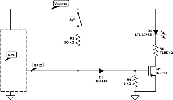
I would like to keep external components such as shift registers to a minimum. Resistors are OK since they are cheap and small, and I am using MOSFETs (NTD4960N: Datasheet ) to drive the LED banks. Essentially, what I am looking to do is drive the MOSFETs with a 200Hz PWM signal to control the LED brightness, but limit the duty cycle to 90%. With that in mind, I would only need a pin to be an output for a maximum of 90% of the time. In the remaining 10% of the time, I want to switch the pin to an input to read the state of a button.
I tried a lot of various configurations to allow the MOSFET to stay OFF when it is supposed to be OFF, regardless of input from the button, and this is the best I could come up with: The supply voltage (VCC) is 5V, so when the button is pressed, about 0. 9V is seen at the transistor gate. This is not enough for the transistor to start conducting, but it can be read by the MCU ADC which has been enabled using the internal 1.
1V reference. So the code drives the MOSFET with a 200Hz PWM signal. The duty cycle will vary with the desired LED brightness, but will not be greater than 90%. During the last 10% of the PWM cycle, the I/O pins are set as inputs (internal pullups disabled, digital input buffers disabled) and the ADC is used to read the state of the pin. The 10k resistor keeps the MOSFET off, and if a button is pressed, 0. 9V is read by the ADC. This value is still not high enough to turn the MOSFET on, so the LEDs stay off, regardless of the button press.
Since the ADC is turned off and on, I discard the first reading and keep the second. This is done in plenty of time before the pin needs to be reset as an output to start the next PWM cycle. Since I am reading multiple buttons, I only read one each duty cycle, then update the ADC multiplxer to read the next button at the end of the next duty cycle - hence, each button is read once every [(# of buttons) * (200Hz).
The PWM and button reads are handled entirely by interrupts while MAIN determines what to do with the state of any particular button. I can post some (or all) of the code if you want. I just thought the description might be enough, and I didn`t want to make this any longer than it already was.
I should have said this the first time, but the MCU supply voltage (VCC) is 5V, the battery voltage (V_bat) is 12V (could be more like 14 on a fully charged battery), and the total LED current (as in the amount going through the FET) will be close to 2A. The LED bank will consist of numerous parallel strings of 3 series LEDs (white, V_LED = 3. 3V) and a series resistor in each string. The pulsed current is around 50mA per string. With 40 or so strings equaling about 2A total. I have tested and verified my ADC version of the circuit as well as the "digital" version presented by DrFriedParts below with a small current (50mA total), but have not yet tested either circuit with the larger current load.
This is the original project that I am redesigning. When I first built this bike light controller, I was new to microconctollers, so it was more of a learning experience than anything else. 🔗 External reference
Related Circuits
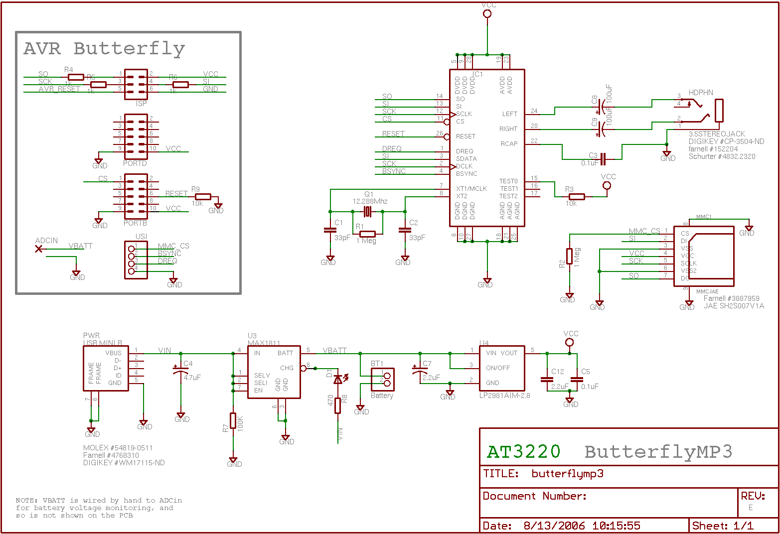
AVR ISP interface (optional but useful if the bootloader is not preferred, if budget constraints prevent the use of JTAG, or if AVR Studio has crashed and disabled on-chip debugging). The following is the updated bill of materials for...
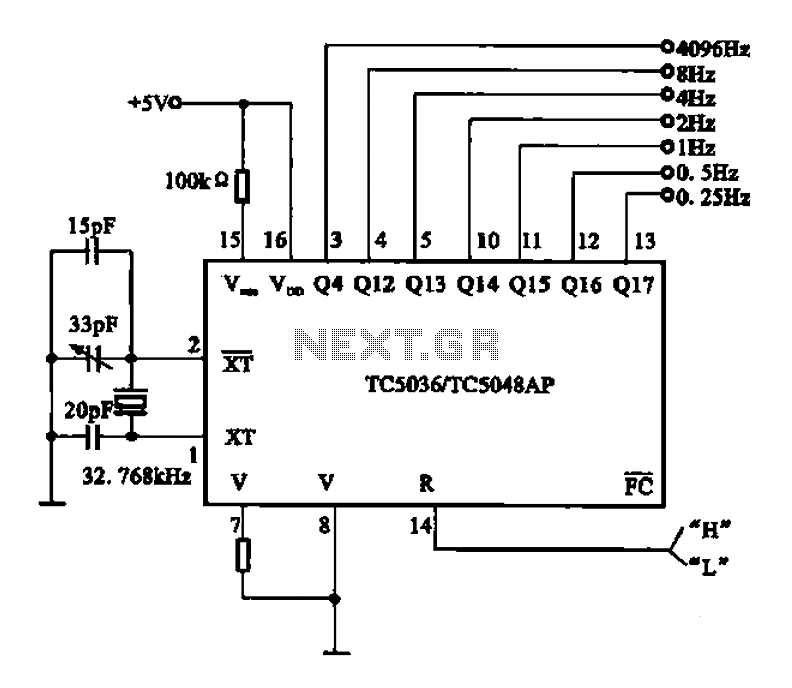
32.768 kHz; In MP3/MP4 devices, mobile phones, laptops, and other digital products, a real-time clock signal generating circuit is utilized, primarily composed of crystal resonators and TC5036/TC5048AP chip oscillators. This setup produces a raw 32.768 kHz crystal oscillator signal,...

A Countdown Timer Circuit is a project submitted by a group of students for their ECE 130 - Computer Application class on August 31, 2006, at the University of St. La Salle, Philippines. The seven-segment decoder is utilized in...

This circuit is capable of generating up to 1 W of audio power to drive a speaker or horn. When the CDS cell is exposed to light, its resistance decreases, activating NOR gate (a). This activation causes gates (a)...
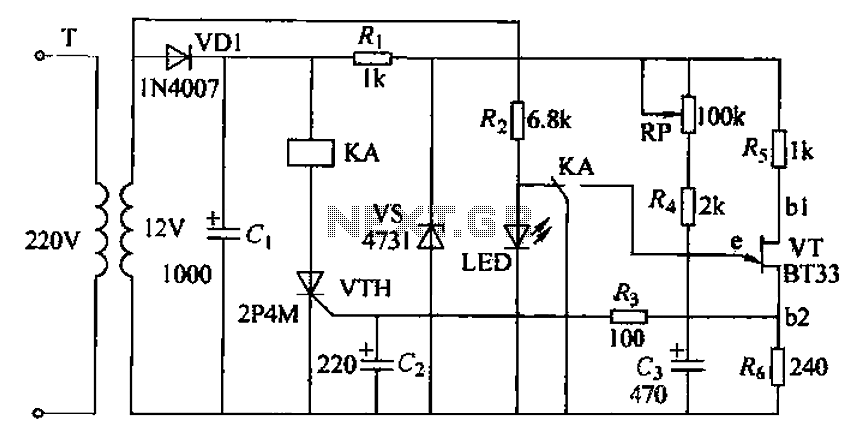
The circuit consists of a delay loop, discriminators, output circuits, power supply, and indicator lights, divided into five parts. The power regulation is achieved through a resistor (R), while the power regulator is constructed using a voltage source. In...
The following circuit illustrates a Cat and Dog Repellent Timer Circuit Diagram. Features include a high-output ultrasonic transmitter and the use of a standard 555 timer. The Cat and Dog Repellent Timer Circuit is designed to emit high-frequency ultrasonic sound...