
AVR Frequency Meter
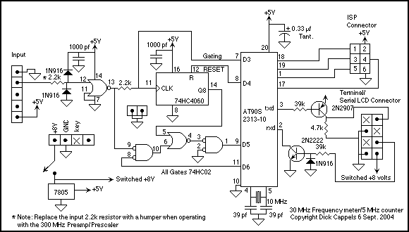
The first phase was to make a high-resolution frequency meter/counter just using the AT90S2313 or ATtiny2313, then to add the external prescaler. Without the prescaler, the maximum input frequency for the frequency meter is 5 MHz or 10 MHz, depending upon the chip you use and the firmware version you choose. With the multi-chip version that includes a prescaler, the maximum input frequency, according to the component specifications, is about 30 MHz - this will vary with individual external prescaler chips and your circuit layout. To summarize, there are three versions of the code available at the top of this page: The 5 MHz single-chip version, which is basically an AT90S2313-10 clocked at 10 MHz and a serial interface, the 10 MHz single-chip version which is basically an ATtiny2313-20 clocked at 20 MHz with a serial interface, and the 30 MHz multi-chip version, which is the same circuit as the 5 and 10 MHz versions, but with the prescaler and quad NOR gate added. In the 30 MHz version, the maximum input frequency for the counter mode (counts until reset via ASCII command) is 5 MHz. The timebase selections between the two versions differ as well. The 30 MHz version has timebases of 0.1, 1, 10, and 100 seconds. Frequency measurement is performed by clocking the 74HC4060, which is capable of being clocked at over 30 MHz, and then counting the overflow pulses from the 8th flip-flop in the 74HC4060's signal path using the AT90S2313-10's on-chip 16-bit counter, which is limited to a maximum input clock rate of 5 MHz (30 MHz/256= 117 kHz). At the end of a frequency measurement period, the input to the 74HC4060 is gated off by turning the bi-directional I/O port, D3, on the AT90S2313-10 from a high impedance input to an output set high. This results in the input signal being dropped across the 2.2k resistor between pin 13 of the 74HC02 and the clock input of the 74HC4060. This technique is borrowed from Chris Krah's LC frequency meter design, where he used this method to gate the input to a counter using an AT90S1200's I/O pin. After moving the contents of the AT90S2313-10's on-chip 16-bit counter to working registers, the AT90S2313-10 toggles the clock pin on the 74HC4060 while decrementing an internal register from $FF until the 74HC4060 toggles again. This way, the contents of the prescaler are transferred to an internal register within the AT90S2313-10.
So far, this accounts for three bytes: the 8 bits of the 74HC4060 and the 16-bit on-chip counter. Overflow from the 16-bit on-chip counter causes an interrupt, during which a fourth byte is incremented. If incrementing this fourth byte results in the byte becoming equal to zero, an internal overflow flag bit is set so that overflows will be denoted in the display. The resulting 32 bits are converted to 9 1/2 decimal digits and sent via the UART to a terminal or display.
In the counting mode, the instrument needs to be able to display the current total count several times per second, so the display appears to be a continuous display of the running total. While displaying the total count, it cannot miss an incoming pulse, and since the prescaler would have to be emptied for each measurement to read out its contents, and while reading out its contents, some pulses could be missed, it is necessary to bypass the prescaler and count directly using the AT90S2313-10's on-chip 16-bit counter. Overflows from the counter cause interrupts which then cause a virtual 16-bit internal register (ZH, ZL) to be incremented, checking for overflow of the Z register, thus providing a 32-bit count. The maximum clock rate for the on-chip 16-bit counter is 5 MHz.
The version of the code that does not use a prescaler (nfmtr040916A.asm) uses the same set of registers as the counting mode for the prescaler version of the code; it just uses the 16-bit on-chip counter and overflows to the Z register.
The first gate that the input signal encounters is a 74HC02, which acts as an inverting buffer. It drives both the 74HC4060, which serves as the 30 MHz prescaler, and the other sections of the 74HC02 that act as a multiplexer to drive the AT90S2313-10's on-chip 16-bit counter with either the output of the prescaler in frequency measurement modes or directly from the output of the buffer in counting mode. Without the buffer, pulses from the gating of the input of the 74HC4060 would appear on the input. The version of the code that does not use a prescaler does not require the buffer or multiplexer; the input signal drives D5 (pin 9) of the AT90S2313-10 directly.
The frequency meter design incorporates multiple configurations to accommodate various input frequencies and enhance measurement accuracy. The integration of the 74HC4060 prescaler allows for high-frequency measurements, while the microcontroller's architecture ensures efficient processing of frequency data. The system's design emphasizes flexibility, enabling the selection of different time bases and accommodating various microcontroller configurations, thus providing a robust solution for frequency measurement applications.This is design for a frequency meter based on AVR microcontrollers. Maximum input frequency is specified to be 30 MHz in the multi-chip configuration, and in single-chip configuration, there are both 5 MHz and 10 Mhz versions operating with 10 and 20 MHz crystals, respectively. All versions have 9 1/2 digit resolution. I have used multi-chip version at 40 Mhz, and depending upon the actual chips you use and your layout, it can work at much higher input frequencies.
The 10 MHz single-chip version using the ATtiny2313 is ideal for use with a X10 or X 100 prescaler. As for microcontroller choice, the requirements for this firmware are that the controller be an AVR with a 16 bit counter, has a ram stack and UART or USART, and the ability to operate at 10 MHz. Some modification may be required to the code to accommodate a USART instead of a UART, a 16 bit stack pointer instead of the 8 bit pointer on the AT90S2313, and the specific controls of the 16 bit counter registers.
I used an AT90S2313 because they are available to me and suitably small. For the 10 MHz input single-chip configuration, you need to use an AVR that can clock at 20 MHz. I used an ATtiny2313-20. When programming the ATtiny2313, remember to select a fuse setting for the internal clock oscillator. The AT90S2313 does not have clock fuse settings. The first phase was to make a high resolution frequency meter/counter just using the AT90S2313 ot ATtiny2313, then to add the external prescaler.
Without the prescaler, the maximum input frequency for the frequency meter is 5 MHz or 10 MHz, depending upon the chip you use and the firmware version you choose. With the multi-chip version that includes a prescaler, the maximum input frequency, according the the component specifications, is about 30 Mhz - this will vary with individual external prescaler chips and your circuit layout.
To summarize, there are three versions of the code available at the top of this page: The 5 MHz single-chip version, which is basically an AT90S2313-10 clocked at 10 MHz and a serial interface, the 10 MHz single-chip versoin with is basically an ATtiny2313-20 clocked at 20 MHz with a serial interface, and the 30 MHz multi-chip version, which is the same circuit as the 5 and 10 MHz versions, but with the prescaler and quad NOR gate added. In the 30 MHz version, the maximum input frequency for the counter mode (counts until reset via ASCII command) is 5 MHz.
The timebase selections between the two version differ as well. The 30 MHz version has timebases of 0.1, 1, 10,and 100 seconds. Frequency measurement is performed by clocking the 74HC4060, which is capable of being clocked at over 30 MHz, and then counting the overflow pulses from the 8th flip-flop in the 74HC4060's signal path using the AT90S2313-10's on-chip 16 bit counter, which is limited to a maximum input clock rate of 5 MHz 30 MHz/256= 117 kHz). At the end of a frequency measurement period, the input to the 74HC4060 is gated off by turning the bi-directional I/O port, D3, on the AT90S2313-10 from a high impedance input to an output set high.
This results in the input signal is then dropped across the 2.2k resistor between pin 13 of the 74HC02 and the clock input of the 74HC4060. I borrowed this technique from Chris Krah's LC frequency meter design in which he used this method to gate the input to a counter using an AT90S1200's I/O pin.
After moving the contents of the AT90S2313-10's on-chip 16 bit counter to working registers, the AT90S2313-10 toggles the clock pin on the 74HC4060 while decrementing an internal register from $FF until the of the 74HC4060 toggles again. That way, the contents of the prescaler is transferred to an register internal to the AT90S2313-10. So far, that accounts for three bytes: The 8 bits of the 74HC4060 and the 16 bit on-chip counter. Overflow from the 16 bit on-chip counter causes an interrupt, during which a fourth byte is incremented.
If incrementing this fourth byte results in the byte becoming equal to zero, an internal overflow flag bit is set so that overflows will be denoted in the display. The resulting 32 bits are converted to 9 1/2 decimal digits and sent via the UART to a terminal or display.
In the counting mode, the instrument needs to be able to display the current total count several times per second, so the display appears to be a continuous display or the running total. While displaying the total count, it cannot miss an incoming pulse, and since the prescaler would have to be emptied for each measurement to read out its contents, and while reading out its contents, some pulses could be missed, it is necessary to bypass the prescaler and count directly using the AT90S2313-10's on-chip 16 bit counter.
Overflows from the counter cause interrupts which then causes a virtual 16 bit internal register (ZH,ZL) to be incremented, checking for overflow of the Z register, thus giving a 32 bit count. The maximum clock rate for the on-chip 16 bit counter is 5 MHz The version of the code that does not use a prescaler (nfmtr040916A.asm) and uses the same set of registers as the counting mode for the prescaler version of the code - it just uses the 16 bit on-chip counter and overflows to the Z register.
The fist gate that the input signal sees, a 74HC02, is an inverting buffer. It drives both the 74HC4060, which is the 30 MHz prescaler, and the other sections of the 74HC02, which act as a multiplexer to drive the AT90S2313-10's on-chip 16 bit counter with either the output of the prescaler in frequency measurement modes or directly from the output of the buffer in the counting mode. Without the buffer, pulses from the gating of the input of the 74HC4060 would appear on the input. The version of the code that does not use a prescaler does not require the buffer or multiplexer - the input signal drives D5 (pin 9) of the AT90S2313-10 directly.
🔗 External reference
Related Circuits
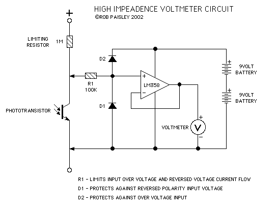
This circuit is designed to provide an inexpensive way to create a High Impedance Voltmeter while making use of an inexpensive analog or digital multimeter. When measuring voltages in high resistance circuits, the resistance of the voltmeter itself has...
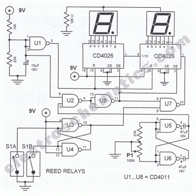
This digital DIY tachometer for bicycles utilizes two reed switches to gather speed information. The reed switches are positioned near the wheel rim, where permanent magnets, attached to the wheel spokes, pass by and activate the switches. The speed...
The AVO VCM 163 is a tube tester capable of measuring tube electrode currents, such as plate and screen currents, as well as mutual conductance simultaneously. It is the most advanced tube tester developed by AVO. The voltages applied...
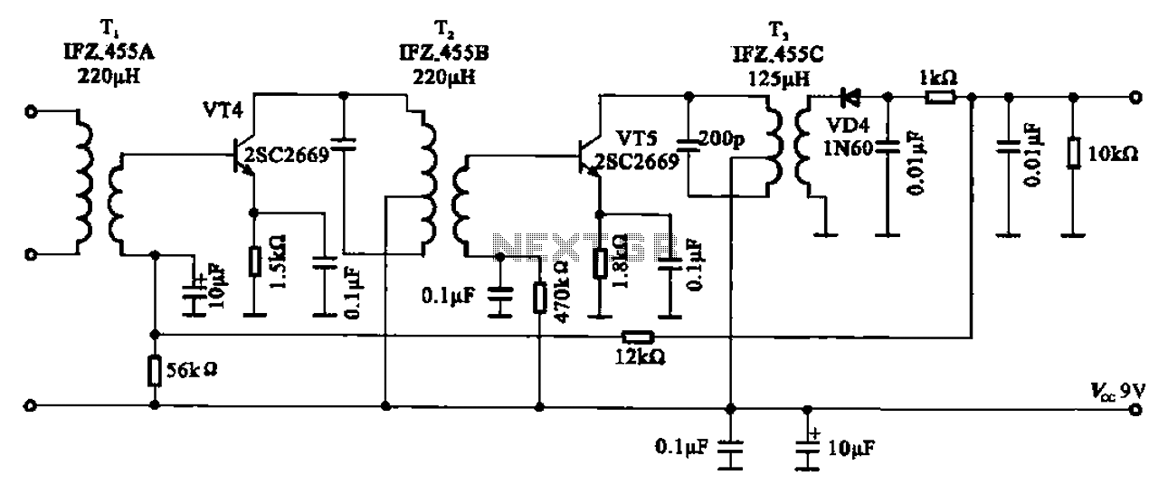
AM radio shows the IF amplifier and detector circuit. The mixer receives the intermediate frequency output signal from the transformer after the device. This signal is applied to the base of the intermediate frequency transistor VT4. The collector load...
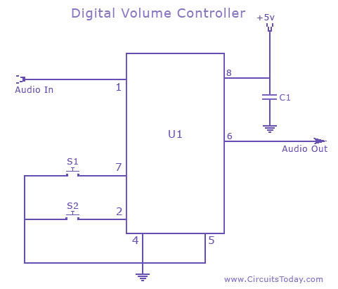
A digital volume control circuit diagram utilizing the DS1669, a potentiometer integrated circuit. This circuit can serve as a digital volume controller for audio amplifiers and various other applications. The digital volume control circuit employs the DS1669 integrated circuit, which...
The apparatus consists of a cavers point detection circuit and a triggering display circuit. The cavers instrument functions as a test probe, which, when held in one hand, can detect acupuncture points by touching the skin with another probe....
Warning: include(partials/cookie-banner.php): Failed to open stream: Permission denied in /var/www/html/nextgr/view-circuit.php on line 713
Warning: include(): Failed opening 'partials/cookie-banner.php' for inclusion (include_path='.:/usr/share/php') in /var/www/html/nextgr/view-circuit.php on line 713