
VCM 163 Valve Characteristic Meter Equipment
The AVO VCM 163 tube tester employs an innovative approach to measuring the performance of electron tubes, combining both analog and digital methodologies. The device is designed to operate using pure 50 Hz sine wave signals, which are crucial for accurate measurements. The application of these sine waves to the plate and screen electrodes ensures that the test conditions mimic actual operating conditions of the tubes.
Diodes D1 and D2 function as rectifier components, converting the alternating current (AC) signal to a usable form while suppressing negative half-waves. This is a unique feature that allows for a straightforward power supply design, negating the need for complex filtering systems typically required in DC applications. The use of diode D4 to apply grid BIAS in anti-phase to the positive voltages exemplifies a clever engineering solution that maximizes efficiency and minimizes component count.
The measurement of mutual conductance is particularly noteworthy, as it utilizes a high-frequency oscillator and amplifier setup. This allows for precise measurements of the grid modulation and the resulting plate current. The system's ability to derive mutual conductance from the relationship between the filtered plate current and the applied grid signal amplitude demonstrates a deep understanding of tube characteristics and operational principles.
The adjustable grid BIAS voltage, selectable across multiple ranges, permits flexibility in testing various tube types. The modulation of the grid voltage with a low amplitude HF signal allows the tester to assess the dynamic response of the tube under test, providing insights into its performance characteristics.
Overall, the AVO VCM 163 stands out as a sophisticated instrument in the field of tube testing, capable of delivering comprehensive and accurate measurements essential for both amateur and professional applications in electronics. Its design reflects a commitment to precision and efficiency, making it a valuable tool for engineers and technicians working with vacuum tubes.The AVO VCM 163 is one of the few tube testers (British: valve tester) being able to measure tube electrode currents, e. g. plate and screen current (fig. 1, left-hand meter movement) as well as mutual conductance (fig. 1, right-hand meter movement) simultaneously. The VCM 163 is the latest and most elaborate tube tester ever built by AVO. All volt ages applied to the electron tube under test are pure 50 Hz line frequency sine waves. The plate (British: anode) as well as the screen electrode via diodes D1 and D2 are supplied with sinusoidal positive half wave voltages (cf. fig. 2). AVO unusually terms rectifier diodes D1 and D2 suppressor` diodes probably due to the fact that they suppress the negative half wave.
Via diode D4 an unsmoothed negative half wave (grid BIAS) is applied to the grid electrode in proper phase relationship, i. e. anti-phase, to the positive electrode voltages. This is quite a clever and economical principle because the power supply becomes extremely simple (among other things no filtering).
In addition power requirement of the line transformer (C core type) is half compared to a DC supply. AVO engineers have evaluated and verified that if alternating electrode voltages are applied in their correct proportions an amplifying tube (by virtue of its property of self-rectification) produces DC plate and screen currents, which for all practical purposes, bear an almost constant relationship to those obtained from its DC static characteristics. In the VCM 163 the following relationship between AC supply and DC static characteristics is implemented: The left meter movement (cf.
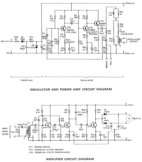
fig. 1) reads DC plate and screen current continuously. As a further consequence of the fictive static characteristic of the VCM 163 test conditions of a tube can be directly obtained from the tube manufacturers published curves or data. Measurement of mutual conductance (= transconductance) is based on a sophisticated operational principle using a transistorized high frequency (HF) oscillator and a frequency selective HF amplifier (fig.
2, High Pass Filter & Amplifier). The grid BIAS signal and the HF signal are added and routed to the grid of the test tube. Detailed schematics are shown in figs 7 & 8. Below, a few voltage measurements performed to clarify the principle of mutual conductance measurement as used in this premium instrument developed by AVO are presented. The amplitude of the negative 50 Hz grid BIAS voltage can be selected in four ranges from 0-100 Volt.
This BIAS voltage is superimposed by a low voltage grid HF signal the amplitude of which is well stabilized. HF modulation of the grid voltage results in a proportional plate HF current. Mutual conductance is derived from the band-pass filtered plate HF current set into relation to the applied grid HF signal amplitude.
Due to the fact that the high frequency grid signal is magnitudes smaller than the Ugrid BIAS amplitude the superimposed grid signal is not readily visible (figure 3). Especially in the horizontal parts of Ugrid recording the superimposed HF grid signal now becomes noticeable as wide traces (fig.
4, arrow). For further clarification of the combined signal to the grid figure 5 illustrates the grid HF signal component using higher amplification (20mV/div) and faster time deflection (50 µs/div). Tubes with low mutual conductance (0-6 mA/V) are measured using a large amplitude grid HF signal whereas tubes with high (0-20 mA/V) or very high mutual conductance (0-60 mA/V) require lower signal amplitudes.
🔗 External reference
Related Circuits
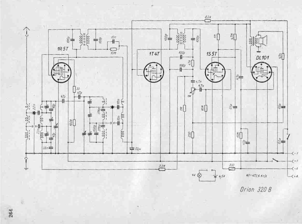
Create a repository of circuits and service data for vintage valve and transistor radios. While many resources are available online, they often come at a cost. The intention is to share circuits and manuals with others rather than profit...
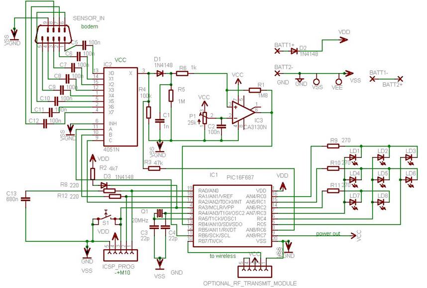
This project illustrates various features of the PIC16F687 microcontroller, including ultra-low power wake-up, serial communications, and nanowatt technology. The device can serve multiple purposes, such as measuring the water level in a rainwater tank or a water tank in...
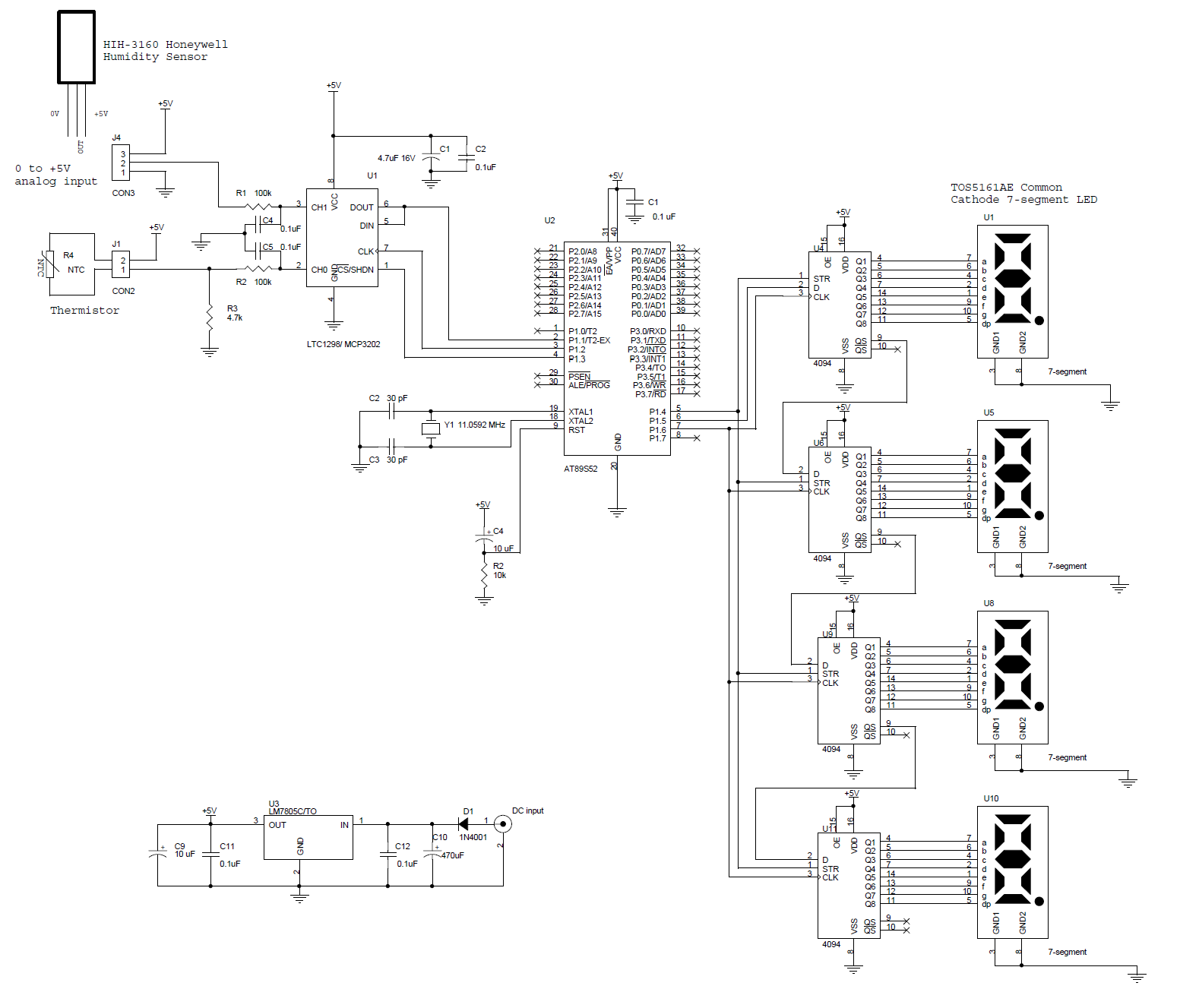
This circuit features a microcontroller AT89S52 paired with a 12-bit ADC LTC1298. The programs are written in C and include digital filtering, interfacing with a 0.5-inch 7-segment LED display. The thermometer provides a sensitivity of 0.1°C. The hardware block...
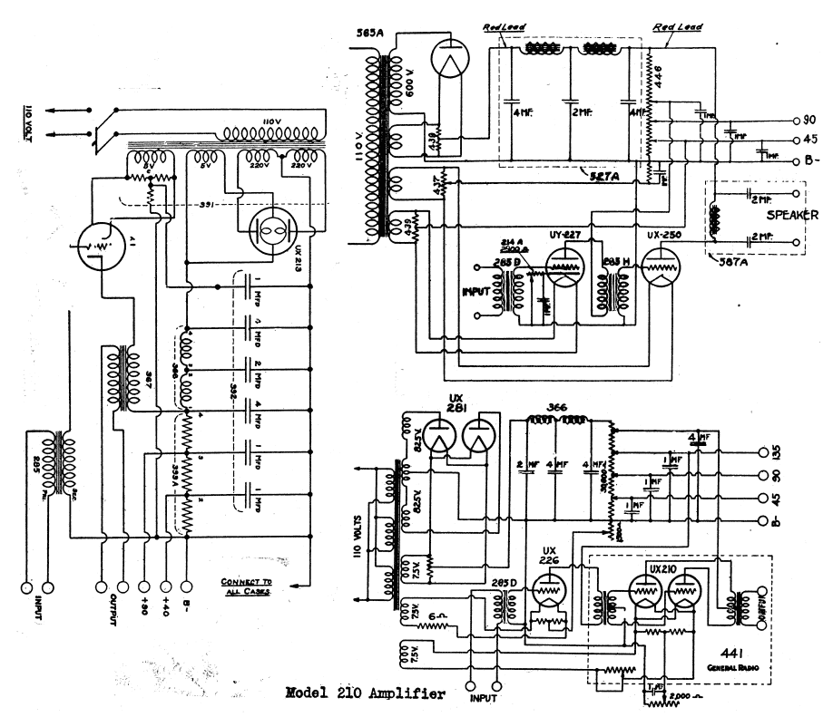
The schematic shows a valve / tube audio power amplifier and a type 390 Rectron B eliminator. The presented schematic illustrates a valve or tube audio power amplifier, which utilizes vacuum tubes to amplify audio signals. This type of amplifier...
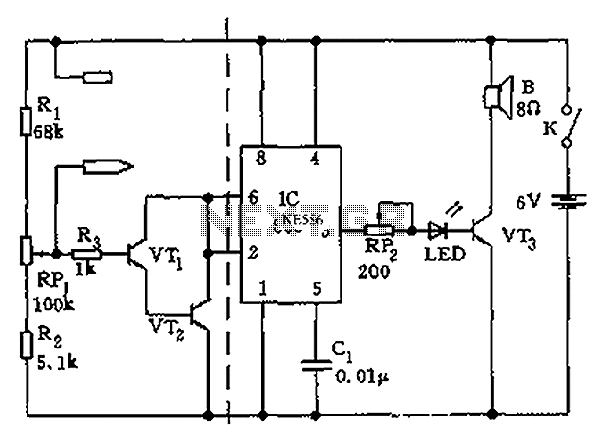
The apparatus consists of a cavers point detection circuit and a triggering display circuit. The cavers instrument functions as a test probe, which, when held in one hand, can detect acupuncture points by touching the skin with another probe....

The circuit utilizes a transistor (VT) and a voltage regulator (VSL) to create a constant current source, employing three regulators to enhance the performance of the regulator circuit. The described circuit employs a transistor (VT) in conjunction with a voltage...
Warning: include(partials/cookie-banner.php): Failed to open stream: Permission denied in /var/www/html/nextgr/view-circuit.php on line 713
Warning: include(): Failed opening 'partials/cookie-banner.php' for inclusion (include_path='.:/usr/share/php') in /var/www/html/nextgr/view-circuit.php on line 713