
avr How to redesign a circuit to use a current sinking IC rather than a current sourcing IC
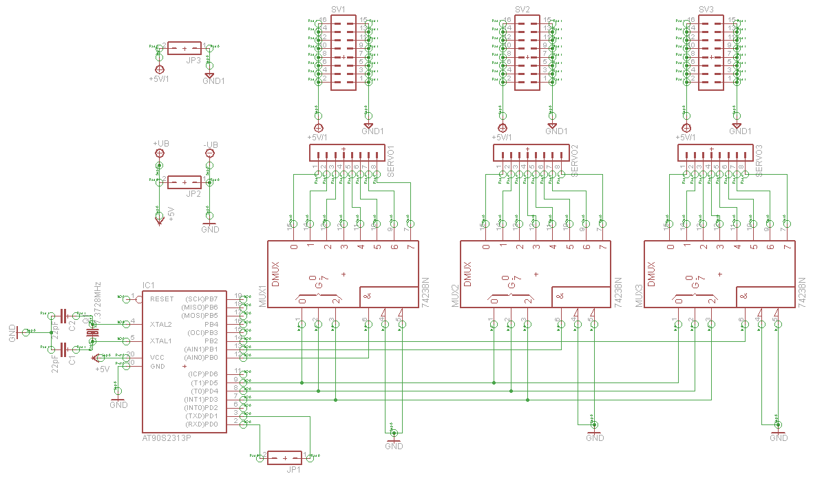
The design of a serial servo controller utilizing 3-8 line demultiplexers, such as the CD74HCT238E, allows for efficient control of multiple PWM signals with minimal I/O pin usage. The CD74HCT238E operates as a high-active demultiplexer, routing incoming signals from the microcontroller to the designated output channels based on the binary address provided. This enables the control of up to 64 servo motors using only 8 pins for the PWM signals and 3 pins for address selection.
In contrast, the CD74HCT138E serves as an active low demultiplexer, which presents a different operational characteristic. When integrating the CD74HCT138E into the circuit, the logic levels must be inverted; this requires adjustments to the circuit design to accommodate the active low configuration. The main difference lies in the way the outputs are activated. With the CD74HCT238E, a high signal on the address lines activates the corresponding output, while the CD74HCT138E requires a low signal for activation.
To successfully transition from the CD74HCT238E to the CD74HCT138E, the schematic must be modified to account for the active low nature of the latter. This involves altering the logic levels in the control signals and potentially introducing additional components, such as pull-up resistors, to ensure that the outputs remain in a defined state when not actively driven low. The complexity of the new design will depend on the existing circuit configuration and how the signals are currently routed.
In summary, while the transition from a current sourcing chip to a current sinking chip introduces additional considerations, it is feasible with careful planning and schematic adjustments. The resulting circuit will maintain the ability to control multiple servo motors while utilizing the active low characteristics of the CD74HCT138E.Building a serial servo controller to learn about electronics and assembly language as part of my hexapod robot project. Quite early on I decided that I needed more I/O channels than my ATTiny2313 that I was using at the time supported so I investigated some 3-8 line demultiplexer chips ( CD74HCT238E `s) which have allowed me to create a 64 channel PWM servo controller with just 8 I/O pins for the PWM channels and 3 address
lines. Anyway. I also bought some CD74HCT138E `s which are active low rather than the active high CD74HCT238E`s. I understand, in principal, the differences between the current sourcing chip that I`m using and the current sinking chips but I don`t really know how to adjust my circuit to use the current sinking chips instead of the current sourcing chips. Note that the reason for asking this question is that I bought a tube of the active low ICs by mistake and I`m curious at how much more complex the schematic and circuit design would need to be for me to make use of them.
🔗 External reference
Related Circuits
The project involves the development of a miniature transmitter suitable for implantation in a rat's body, capable of transmitting 416-bit data samples at a rate of 400 samples per second. It is designed to have a detection range of...

The AVR 8-Bit RISC microcontroller from Atmel is a widely used microcontroller. This microcontroller integrates EEPROM, RAM, an Analog to Digital converter, numerous digital input and output lines, timers, UART for RS-232 communication, and various other features. An article...
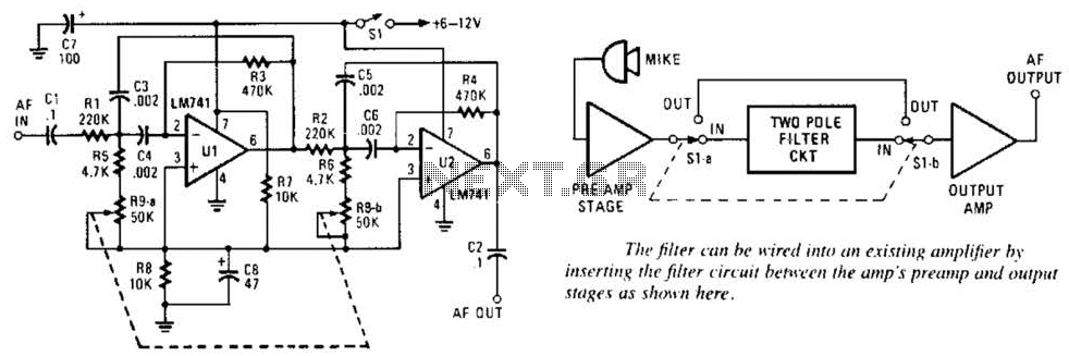
This variable-frequency audio bandpass filter is constructed using two 741 operational amplifiers (op amps) connected in cascade. Both op amps are configured as identical RC active filters, enhancing the selectivity of the overall circuit. The filter has a tuning...

The following circuit is a PC thermometer utilizing the DS1621. Features include the ability to plug into any available PC COM port, a temperature range of -20 to 125°C, and the capability to display temperatures in both Celsius (°C)...
Switch S2 is used for increasing and switch S3 is used for decreasing the volume. Similarly, switches S4 and S5 are provided for second channel (right channel) volume control. Also, pin 14 of IC2 can be connected to IC...
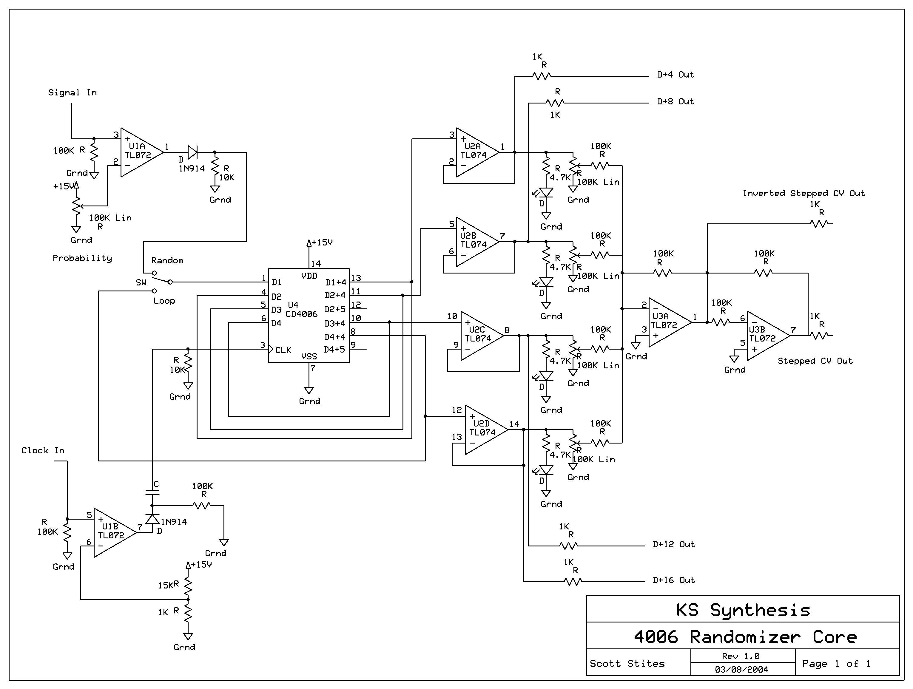
The mechanics of the Quantized Random Voltage function are intriguing. Instead of having fixed quantization steps for each output of the 4006 shift register, it is proposed to make the voltages adjustable through potentiometers. The Quantized Random Voltage function...
Warning: include(partials/cookie-banner.php): Failed to open stream: Permission denied in /var/www/html/nextgr/view-circuit.php on line 713
Warning: include(): Failed opening 'partials/cookie-banner.php' for inclusion (include_path='.:/usr/share/php') in /var/www/html/nextgr/view-circuit.php on line 713