
AVR Interrupts and binary counter

The Atmega8 microcontroller operates at a voltage range of 2.7V to 6V and can be programmed using the AVR-GCC toolchain. In this schematic, the connections for the buttons to pins 4 and 5 of port D are essential for enabling the external interrupts. Pull-up resistors are typically used to ensure that the pins read a high state when the buttons are not pressed. When a button is pressed, the corresponding pin is pulled low, triggering the interrupt.
The GICR register controls the interrupt enable bits, allowing for precise control over which interrupts are active. By configuring the ISC bits in the MCUCR register, the sensitivity of the interrupts can be tailored to specific applications. In this case, setting ISC01 and ISC00 to 1 and 0, respectively, configures INT0 to trigger on a falling edge, while ISC10 and ISC11 are set similarly for INT1.
The handling of the interrupts is crucial for the functionality of the binary counter. Upon triggering, the ISR (Interrupt Service Routine) can be programmed to increment or decrement the REG variable, which holds the current count. The output to port C allows the status of the counter to be visually represented by the six LEDs, providing immediate feedback on the current count.
In addition to the basic functionality described, further enhancements can be made to the program. For instance, debouncing logic can be implemented to prevent multiple triggers from a single button press due to mechanical bounce. Furthermore, additional features such as long-press detection or multi-button combinations could expand the capabilities of the circuit.
The schematic diagram should include all necessary components, including the Atmega8 microcontroller, buttons, pull-up resistors, and the six LEDs connected to port C. Proper labeling of each component and clear connections will facilitate understanding and reproduction of the circuit.In previous article about the Atmel AVR We have only blinked with LEDs, without influence of events outside the microprocessor. All ports operated only as outputs, there was no input. Now we will show how to connect control buttons to the microcontroller and how to the INTO and INT1 pins as inputs.
To demonstrate this, I chose the Atmega8 (You can also use the newer Atmega8A). The buttons are connected to pins 4 and 5, which are bits 3 and 4 of the port D, but also have an alternative function - INT0 and INT1. These alternative functions are in our interest. They are external interrupt sources. If these interrupts are enabled, you can use these inputs to trigger the interrupt handler. INT1 interrupt is enabled using the most significant bit in register GICR. Interrupt INT0 is enabled using the second highest bit. Enabling both interrupts we do by setting the two upper bits of GICR to 1: Next, we have to select what will trigger the interrupt - the interrupt sensitivity.
This is done by using the MCUCR registr. Sensitivity of INT0 is chosen by combination of two bits - ISC01 and ISC00. Sensitivity INT1 is chosen bits ISC10 and ISC11. In our example, we want sensitivity to the falling edge, and therefore each pair is set to 1 0. We can do it this way: Pressing the button now initiates the appropriate interrupt handler. In our example, this is the increment / decrement the working register REG and subsequently sending its state on output, which is a port C - its first 6 bits. Its status is indicated by 6 LED. Now you have built the binary counter, you can press a one button to add 1 and second button to substract 1.
Schematic diagram of this experimental circuit you can see below. This video on the bottom of this page demonstrates the function. You can certainly find a lot of other things to which buttons can be used :). When no interrupt is being executed, the program loops it the endless loop (called SMYCKA in the cource code). There`s nothing in the loop, but you can add something. The program is available for download below. 🔗 External reference
Related Circuits
The NanoVM is a java virtual machine for the Atmel AVR ATmega8 CPU, the member of the AVR CPU family used e.g. in the DLR Asuro robot, manufactured by AREXX engineering. With the NanoVM, the Asuro can be programmed...
The number of pulses at the input can be visually confirmed by connecting a light-emitting diode to the output of the counter. In this circuit, a counter is utilized to count the number of input pulses. The output of the...
Useful as a transmitter tune-up meter or an RF sniffer, this is an RF field strength indicator that is loosely based on the Broad Band RF Field Strength Probe, described elsewhere. It detects RF via a square law detector,...
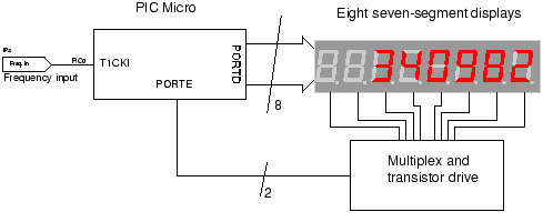
The circuit employs a straightforward approach for direct frequency measurement, which is user-friendly but results in the number of displayed digits varying with the input frequency. To consistently display all digits, a method known as reciprocal counting can be...
The objective of this project is to create a controller-based model that counts the number of individuals entering a specific room and activates the lighting accordingly. This is achieved through the use of sensors that detect the current number...

AVR has two different programming modes called Parallel Programming Mode (Parallel Mode) and Serial Downloading Mode (ISP mode). In Parallel Mode, the programming is done using multiple data lines simultaneously, allowing for faster programming speeds. This mode is typically...