
pic frequency counter using 16f877a
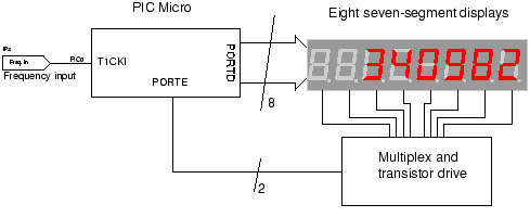
The described frequency measurement circuit is designed to provide a real-time display of frequency values based on the input signal. The direct frequency measurement technique operates by counting the number of cycles of the input frequency over a defined time interval. The display output is directly proportional to the frequency being measured, which can lead to variations in the number of digits shown based on the input frequency level. For example, a higher frequency input may yield fewer displayed digits, while a lower frequency input could result in a more extensive numeric output.
To achieve a stable and consistent display of all significant digits regardless of frequency variations, the reciprocal counting technique can be implemented. This method involves calculating the reciprocal of the frequency, thereby allowing for a constant number of displayed digits. However, implementing reciprocal counting introduces complexity, as it requires the use of floating-point arithmetic or fixed-point routines. These routines are essential for managing the mathematical operations involved in calculating the reciprocal values accurately.
The hardware limitations of the circuit also play a crucial role in its design. The requirement for constant time routines is critical to maintain accurate frequency measurements. These routines ensure that the counting process is synchronized with the input signal, providing reliable and precise frequency readings. The challenge lies in the balance between the simplicity of the direct measurement method and the need for more complex algorithms to achieve a consistent display.
Overall, the circuit design must carefully consider the trade-offs between ease of implementation and the accuracy of frequency representation, especially when displaying all digits consistently across varying input frequencies.It uses the simpler method of direct frequency measurement which is easy to do but means that the number of digits displayed depends on the input frequency. If you want to display all digits all the time there is a technique called reciprocal counting- but this requires floating point (maybe fixed point) routines and would be difficult to implement with this hardware since it needsconstant time routinesto count accurately.
🔗 External reference
Related Circuits
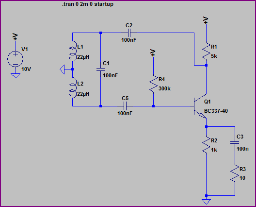
A Hartley Oscillator circuit can be constructed using a pair of series-connected coils. Two 22mH fixed inductors were utilized on a breadboard along with other necessary components. Testing the transistor amplifier independently indicated proper functionality; however, there is no...
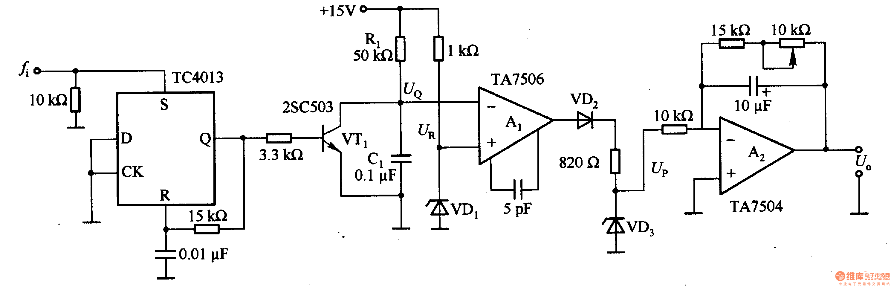
This circuit can convert an input frequency ranging from 0 to 100 Hz into an output voltage of 0 to 10 V. It utilizes the TC4013 monostable multivibrator to shape and amplify the input pulse, which has a width...
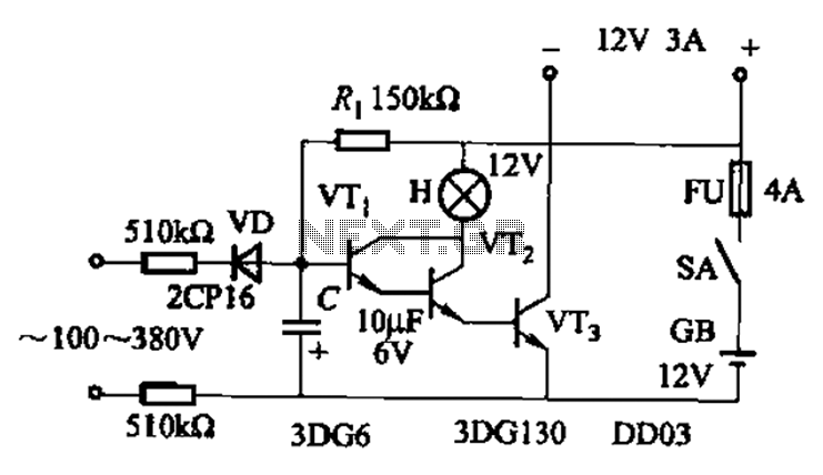
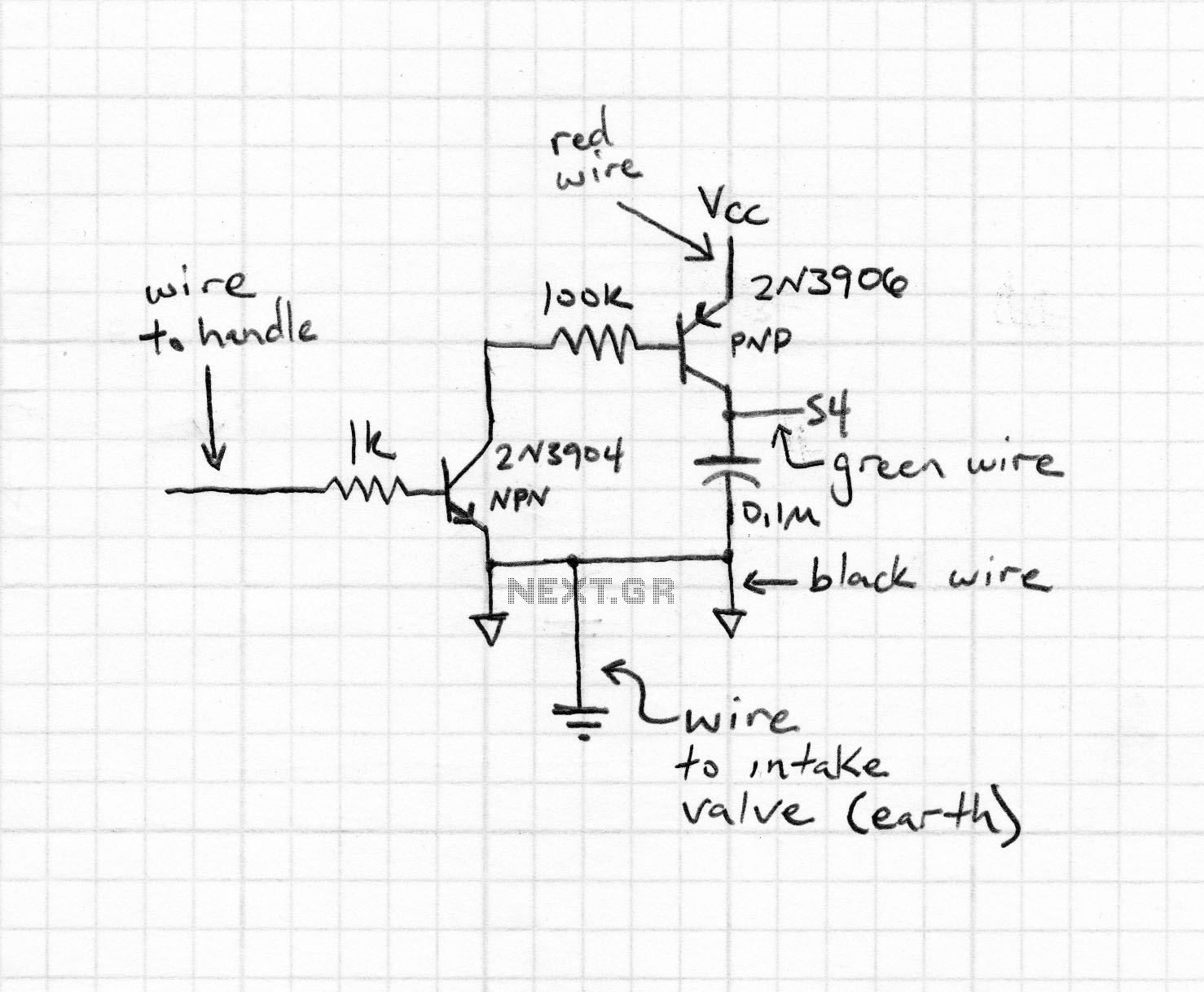
An AC-DC power supply without a power switching circuit is typically utilized for lighting load circuits. Once the power grid is restored, the standby power supply automatically switches on. An automatic switching circuit using a transistor is implemented, with...
The TV transmitter presented generates a stream containing four TV programs and broadcasts it on a frequency compliant with the DTT standard. It is suitable for integration into an antenna system and can utilize audiovisual channels generated on-site or...
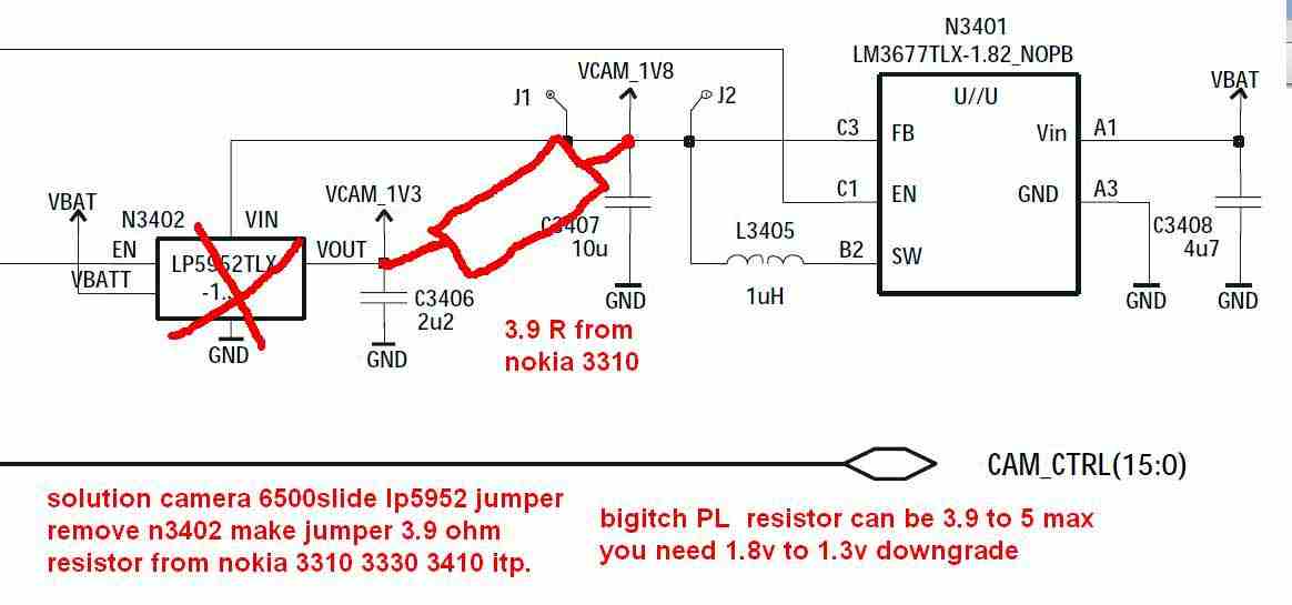
The Nokia 6500 camera issue, characterized by messages such as "camera operation failed" or a blank camera display, can potentially be resolved through a simple workaround. The accompanying images illustrate the Nokia 6500 slide camera problem and suggest creating...
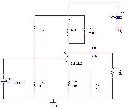
A simulation of a 27 MHz transmitter circuit is to be conducted using PSPICE. The circuit diagram is provided as Figure 1 in the following content. The 27 MHz transmitter circuit typically consists of several key components, including an oscillator,...
Warning: include(partials/cookie-banner.php): Failed to open stream: Permission denied in /var/www/html/nextgr/view-circuit.php on line 713
Warning: include(): Failed opening 'partials/cookie-banner.php' for inclusion (include_path='.:/usr/share/php') in /var/www/html/nextgr/view-circuit.php on line 713