
high voltage parallel programmer avr

The AVR microcontroller family supports two distinct programming modes: Parallel Programming Mode and Serial Downloading Mode (ISP mode). In Parallel Programming Mode, multiple data lines are engaged simultaneously, facilitating rapid programming of the microcontroller. This mode is advantageous in manufacturing environments where numerous devices require simultaneous programming, thereby enhancing efficiency and reducing programming time.
On the other hand, Serial Downloading Mode, commonly referred to as In-System Programming (ISP), employs a single data line for communication. This method allows for programming while the microcontroller remains installed within the circuit, which is beneficial for firmware updates and debugging. The ISP mode is particularly advantageous during the development phase, as it enables developers to modify and upload new firmware without the need for desoldering the microcontroller from the PCB.
Both programming modes are essential for different applications, with Parallel Mode being preferred for high-volume production and ISP mode being ideal for flexible and iterative development processes. Understanding the characteristics and applications of each mode is crucial for optimizing programming strategies in various electronic projects.AVR has two different programming modes called Parallel Programming Mode (Parallel Mode) and Serial Downloading Mode (ISP mode). At the Parallel Mode,.. 🔗 External reference
Related Circuits
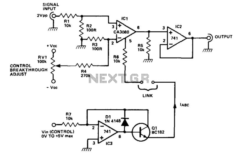
The CA3080 can be utilized as a gain-controlling device. The input signal is attenuated by resistors R1 and R2 so that a 20 mV peak-to-peak signal is applied to the input terminals. If this voltage exceeds a certain threshold,...
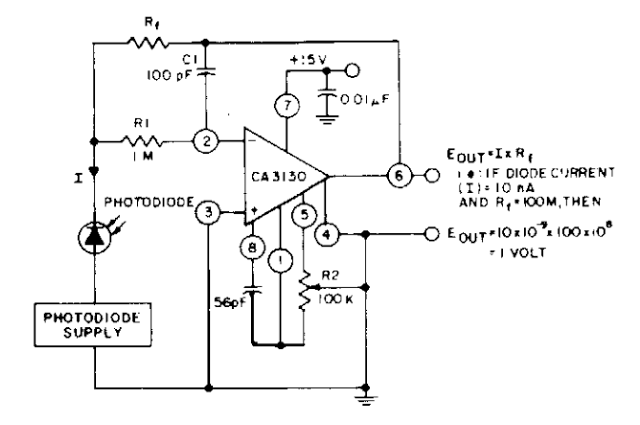
The photodiode current-to-voltage converter circuit employs three CA3130 BiMOS operational amplifiers, designed for applications that require sensitivity to sub-picoampere input currents. This circuit generates a ground-referenced output voltage that is directly proportional to the input current flowing through the...
A tiny speedometer/trip computer was constructed using an Atmel ATTiny2313 microcontroller and an HD44780-compatible character LCD display, along with a reed switch and magnets. This device measured the speed of a soapbox derby cart by attaching a permanent magnet...
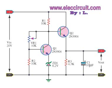
This circuit maintains a constant voltage, with an adjustable output voltage. It serves to reduce the input voltage while keeping the voltage constant. The amplifier model used is the Q1 2N3904 in a common-emitter configuration. This configuration allows the...
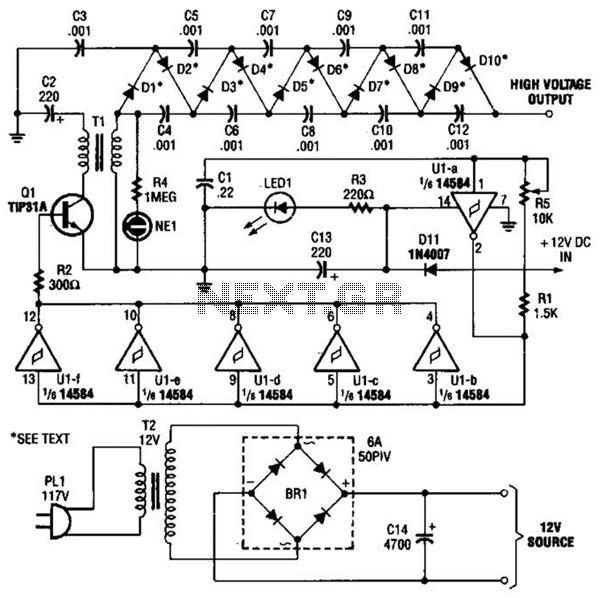
In the miniature high-voltage DC generator, the circuit receives input from a 12 V DC power supply, which is amplified to produce a 10,000 V DC output. This process induces a pulsating signal of opposite polarity in the secondary...
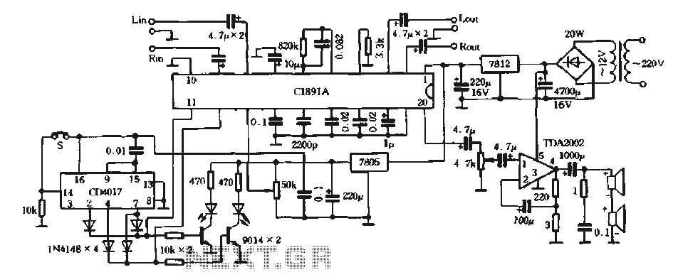
The surround processing section C1891A is a product from Sony Corporation of Japan that features a four-dimensional home theater surround processing circuit. It includes a parent roll phase-shifting circuit and a matrix surround sound amplifier. Additionally, it provides three...