
AVR ISP ScoketBoard
The AVR ISP SocketBoard is designed to facilitate the programming of various AVR microcontrollers in a versatile and cost-effective manner. Its architecture allows for easy connectivity to both in-system programming tools and external power sources, while its multiple socket options cater to a range of microcontroller types, ensuring compatibility and flexibility for different applications. The implementation of adjustable voltage regulators enhances the board's functionality, providing users with the ability to adapt to various programming requirements, particularly for low-voltage microcontrollers. The careful consideration of current limiting and protection features further reinforces the reliability of the SocketBoard, making it an essential tool for developers and manufacturers working with AVR microcontrollers. The overall design promotes efficient programming processes, whether in a manufacturing environment or for individual development purposes, thus streamlining workflows and reducing the need for expensive programming equipment.Most Atmel AVR microcontrollers can be programmed via their in-built serial programming interfaces (SPI). This method is ideal for in-situ programming, such as might be used in manufacturing or for firmware development or field upgrades.
In this scenario, the micro remains in its socket on the application board and a low-cost in-system programmer(ISP) is plugged into a dedicated programming header. In other words, the microcontroller does not have to be removed from its socket and plugged into a parallel programmer each time a firmware update is required. However, in some cases it is desirable to programme a microcontroller stand-alone, such as when the application board is unavailable or doesn`t include an ISP (or JTAG) header.
A low-cost method of stand-alone programming might also be useful where a batch of chips is needed for a small prototype run and the cost of a commercial parallel programmer is prohibitive. This is where the AVR ISP SocketBoard comes in. It provides the minimum of functions necessary to support in-system programming, including a regulated power supply, clock source and microcontroller IC socket.
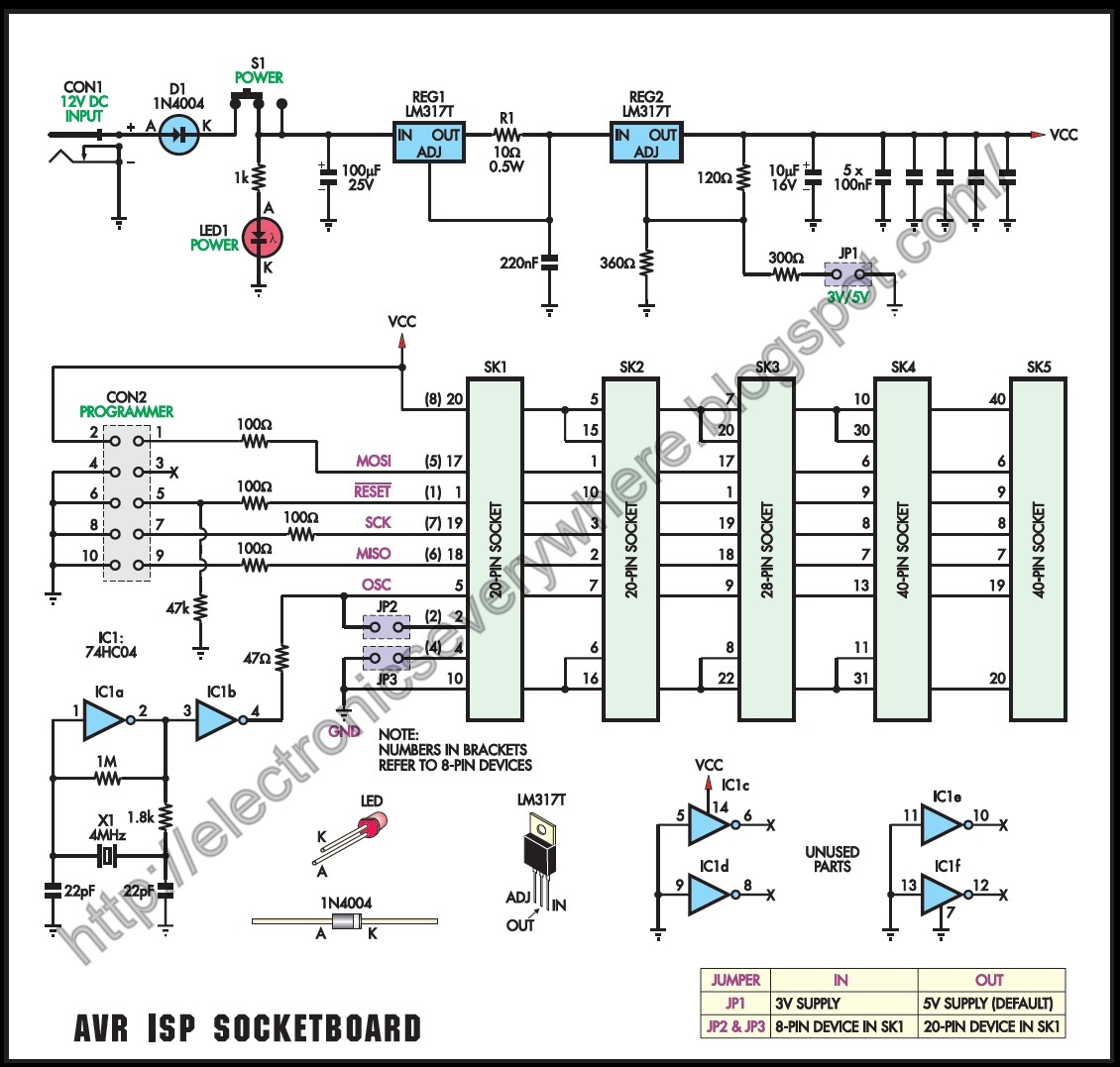
Just connect your in-system programmer to a PC, plug its ISP cable into the SocketBoard`s on-board header and add a DC plugpack. You`re then ready to start programming! As you can see from the photos, the SocketBoard contains five programming sockets. Why so many Well, we`ve provided one programming socket for each group of micros with common SPI pinouts.
This allowed us to eliminate the switching logic that would have been required if we`d used just a single, 40-pin socket, so greatly simplifying design and construction. We expect that many constructors will install just one or two programming sockets (depending on their requirements), to keep costs as low as possible.
The overlay diagram (Fig. 2) lists specific device types and the sockets (SK1 to SK5) that support them. For example, to program the ATM ega16, socket SK4 must be installed. For cases where quantities of chips need to be programmed, the board will accept standard zero insertion force (ZIF) sockets as well. There is absolutely no need to install ZIF sockets (as shown in our photos) for occasional programming; this would simply be expensive overkill.
The unit can be powered from a 12V DC 150mA (or higher) unregulated plugpack, which also powers the ISP programmer when it`s plugged into the on-board header. As mentioned, the SocketBoard provides the minimum of functions necessary to support in-system programming.
As stated, this includes a series of programming sockets to accommodate the different types of AVR micros, a regulated power supply, and a clock source. The power supply is based around two series-connected LM317 adjustable positive regulators (see Fig. 1). The first regulator acts as a current limiter. In normal operation, it performs no function. However, should the current through R1 increase to a level where about 1. 25V is dropped across it, REG1 begins to reduce the voltage at its OUT terminal. In effect, REG1 then acts as a constant current source, limiting output current to a In normal operation, the complete setup consumes an average of about 20 to 40mA, depending on the type of in-system programmer connected.
The remaining capacity (85 to 105mA) leaves a comfortable margin, which in most cases is still low enough to preserve any micro that might be accidentally reversed in a socket. It also protects other components if an internally short-circuited micro is plugged into a socket. The second regulator (REG2) is configured as a conventional voltage regulator. Without JP1 installed, it produces +5V to power the system. Installing JP1 reduces this to +3V. Some constructors may find this lower voltage useful for verifying the memory in micros that are destined for 3V systems.
As well as power, AVR micros require a clock source for their internal programming circuits to o 🔗 External reference
Related Circuits
The primary advantage of this programmer is its capability to safeguard both the target device and the PC from unexpected voltages when either side is powered down. The buffers utilized are open-drain, with each buffer connected to the Vcc...
Introduction: Token Display Systems are ideal for banks, airports, public dealing offices, hospitals, doctors' clinics, restaurants, and other locations where people must wait in line. These systems allow customers to wait comfortably without standing in line; they only need...
This is a design for a frequency meter based on AVR microcontrollers. Maximum input frequency is specified to be 30 MHz in the multi-chip configuration, and in single-chip configuration, there are both 5 MHz and 10 MHz versions operating...
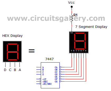
This circuit defines seven levels in a reservoir. The sensed values are connected to an encoder circuit, which consists of a 74148 integrated circuit (IC), functioning as an 8-line to 3-line encoder. The next section features a HEX display,...

The digital display temperature detection circuit utilizes a precision digital display to indicate temperature readings. The circuit employs the MC1403, which outputs a reference voltage, with the potentiometer RP5 setting the reference value for the inverting terminal (a) of...
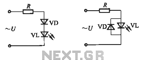
Light-emitting diodes (LEDs) can be powered using direct current (DC), alternating current (AC), and pulse drivers. A typical buck LED display circuit is illustrated in Figure 13-1. The current-limiting resistor (R) for LED tubes can be calculated using the...
Warning: include(partials/cookie-banner.php): Failed to open stream: Permission denied in /var/www/html/nextgr/view-circuit.php on line 713
Warning: include(): Failed opening 'partials/cookie-banner.php' for inclusion (include_path='.:/usr/share/php') in /var/www/html/nextgr/view-circuit.php on line 713