
Digital display temperature detection circuit
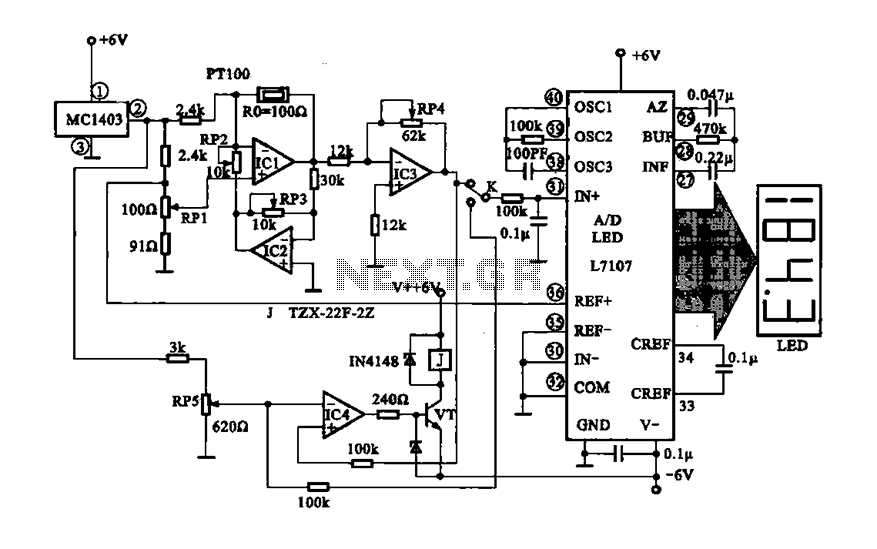
The digital display temperature detection circuit is designed to provide precise temperature measurements and control heating elements based on the detected temperature. The core components of this circuit include the MC1403 voltage reference, which stabilizes the reference voltage necessary for accurate comparisons within the circuit. The potentiometer RP5 allows for fine-tuning of the reference voltage, enabling the user to set specific temperature thresholds for activation.
The thermistor PT100 serves as a temperature sensor, whose resistance varies with temperature changes. This property is exploited in the feedback loop of IC1, where the thermistor's resistance directly influences the feedback signal. As the temperature increases, the resistance of the thermistor decreases, leading to an increase in the feedback to IC1. This change modifies the gain of IC1, which is crucial for maintaining stable operation and ensuring that the output signal accurately reflects the temperature changes.
The output from IC1 is compared to a reference voltage from IC3, which is configured to provide a stable reference point. The result of this comparison is fed into the non-inverting input of IC4. When the output voltage from IC1 exceeds the reference voltage, the output of IC4 changes state, which in turn activates the transistor VT. This transistor acts as a switch to control a relay that can turn on heating elements or other devices as necessary, ensuring that the system responds promptly to temperature changes.
Furthermore, the voltage representing the measured temperature is routed to the A/D converter L7107. This component converts the analog voltage signal into a digital format, allowing for easy monitoring and display of temperature readings on a digital interface. The digital display provides real-time temperature information, facilitating user interaction and oversight of the temperature control process.
Overall, this circuit effectively integrates temperature sensing, feedback control, and digital display technologies to create a robust temperature detection and control system suitable for various applications in industrial and laboratory environments.Digital display temperature detection circuit Precision digital display shows the temperature detection control circuit, MC1403 pin output reference voltage, the potentiometer RP5 setting the reference value to IC4 inverting terminal (a). Thermistor (temperature sensor) PT100 added ICI negative feedback loop, the temperature on the heat -sensitive resistance value will also change, so the amount of negative feedback IC1 changes, ICI gain change with, lC] output formed by IC3 comparison voltage is applied to the noninverting input of IC4, output RP5 compare. Compare voltage increases so that VT conduction, relay control heating and other equipment running. At the same time the temperature represents the voltage value supplied to A/D converter L7107, the analog signal into a digital signal, via the monitor through the digital temperature value is displayed,
Related Circuits
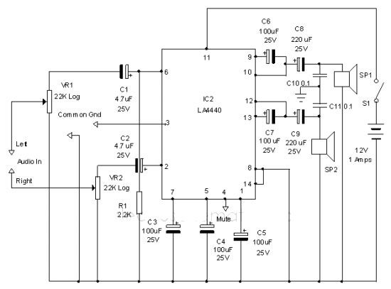
The LA4440 audio amplifier IC can be utilized to design a straightforward stereo power audio amplifier project, capable of delivering 6 watts of output power into an 8-ohm load. This audio amplifier IC features a minimal number of external...
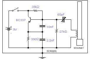
This basic oscillator will detect the Earth magnetic field. The ferrite rod and coil are taken from an old Medium Wave receiver and a small magnet is glued at one end. Tune to a medium wave commercial station until...
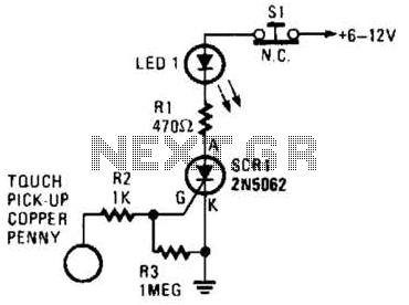
When the touch-on contacts are bridged, pin 6 of U1 goes low, which forces its output (the set output) at pin 4 to go high. That high divides along two paths; in one path, the output is applied to...

A micro mixer circuit is designed to be simple, affordable, compact, and versatile. This circuit can mix up to four input channels, including microphone signals, FM tuners, AUX, and other signals, as illustrated in Figure 1. The operation begins...
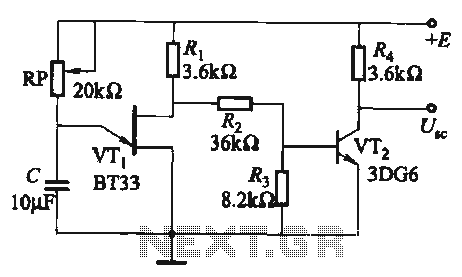
The circuit comprises a single-junction transistor VTi, a resistance Ri, a potentiometer RP, and a capacitor C, forming a relaxation oscillator and an amplifier transistor VTz. The adjustment potentiometer RP allows for changing the relaxation oscillation frequency, providing a...

This schematic is directly sourced from the Altera ByteBlaster datasheet or manual, which provides comprehensive details regarding the connector's functionality and pin connections. It is advisable to review the datasheet available on their website or through a search engine...
Warning: include(partials/cookie-banner.php): Failed to open stream: Permission denied in /var/www/html/nextgr/view-circuit.php on line 713
Warning: include(): Failed opening 'partials/cookie-banner.php' for inclusion (include_path='.:/usr/share/php') in /var/www/html/nextgr/view-circuit.php on line 713