
High Impedance DC Voltmeter using MOS Op-Amp

The high-impedance voltmeter circuit typically employs operational amplifiers (op-amps) configured in a non-inverting arrangement to ensure minimal loading on the circuit under test. This configuration is essential for accurately measuring the voltage without significantly affecting the circuit's operation.
The input stage of the voltmeter consists of a precision op-amp, which is chosen for its high input impedance, usually in the range of megaohms, and low offset voltage to enhance measurement accuracy. The op-amp's non-inverting input receives the voltage to be measured, while the inverting input is connected to a feedback resistor network that sets the gain of the amplifier.
To convert the output voltage of the op-amp to a readable format, a digital voltmeter (DVM) or an analog display can be used. If a DVM is employed, an Analog-to-Digital Converter (ADC) may be integrated into the circuit, allowing for digital readouts of the measured voltage. The circuit may also include a reference voltage source to calibrate the measurement range, ensuring that the displayed voltage accurately corresponds to the input voltage.
Additional components in the circuit may include protection diodes to prevent damage from overvoltage conditions, as well as filtering capacitors to minimize noise and stabilize the readings. The layout of the circuit should be carefully considered to reduce interference and ensure accurate measurements, particularly in environments with fluctuating electrical noise.
Overall, this high-impedance voltmeter design is suitable for applications where precise voltage measurements are required without impacting the performance of the circuit being tested.The circuit was designed for the purpose of creating a voltmeter with high impedance that would measure Direct Current voltages across any types of circui. 🔗 External reference
Related Circuits
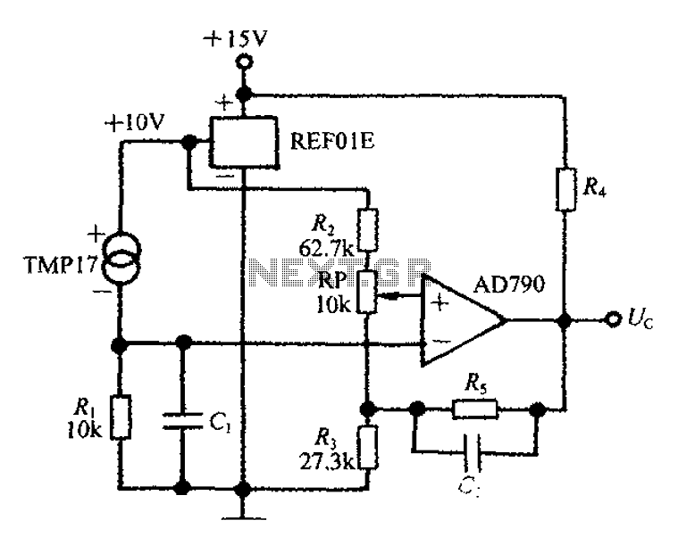
An adjustable thermostat controller circuit is widely used in everyday applications, such as for maintaining a constant temperature in soldering irons. The circuit utilizes the TMP17 sensor along with the REF01E voltage reference to ensure a stable 10V supply...
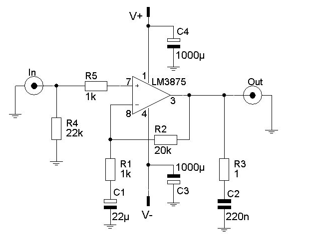
The LM3875 is a high-power audio amplifier capable of delivering 56W of continuous average power to an 8-ohm load. Its performance is enhanced by maximum instantaneous auto temperature protection circuitry, placing it in a superior class compared to discrete...
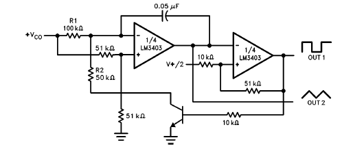
The LM3403 op-amp family includes the LM3303, which is a monolithic quad op-amp known for its high gain. It features a compensated internal frequency, allowing it to operate effectively across a wide range of voltages from both single and...

This design circuit is a tachometer circuit based on the LM2907 integrated circuit, which can provide zero-crossing data to a digital system. At each zero crossing of the input signal, the charge pump alters the state of capacitor C1...
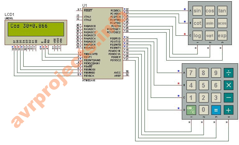
This project provides a straightforward scientific calculator utilizing an AVR microcontroller. It features two keypads as illustrated in the circuit diagram, and the results are displayed accordingly. The scientific calculator circuit based on an AVR microcontroller is designed to perform...
The circuit is designed to deliver approximately 10% distortion on a 4 Ohm to 8 Ohm loudspeaker. The LM4756 amplifier can output 7W of power. Utilizing four pairs of 2SC5200 and 2SA1943 transistors, this configuration can generate around 500W....