
How LCD Display Interface Circuit works

The LCD operates on the principle of manipulating light through liquid crystals, which change their orientation when an electric field is applied. This change alters the light's passage through the liquid crystals, enabling the creation of images. The application processor sends pixel data to the LCD via a connector, with a sequence of signals that dictate the color and brightness of each pixel.
The LED backlight is typically arranged in a matrix behind the LCD panel, providing uniform illumination. This backlight is essential for visibility, as it enhances the contrast of the displayed images. The power supply circuit is designed to deliver the necessary voltage and current to both the LCD and the LED backlight, ensuring stable operation.
The electromagnetic interference (EMI) filtering circuit is critical in preventing external noise from affecting the LCD's performance. This circuit typically includes capacitors and inductors that suppress high-frequency noise, thereby maintaining signal integrity.
In the schematic diagram, various components such as resistors, capacitors, and connectors are shown, depicting their interconnections on the printed circuit board (PCB). The layout is optimized to minimize signal degradation and to manage heat dissipation effectively. Each component is strategically placed to ensure that the LCD operates efficiently within the mobile device's compact design.
Overall, the integration of the LCD with the application processor, LED backlight, and power supply circuit is fundamental to achieving high-quality display performance in mobile phones, enabling vibrant and clear visuals for users.An LCD -liquid crystal display is an electronically-modulated optical device made up of any number of pixels filled with liquid crystals and arrayed in front of a light source (backlight) or reflector to produce images in color or monochrome. The block diagram shows the LCD gets a data source from the application processor, so therefore LCD is bei
ng controlled by the application processor to produce a detail images, LED is a light emitting diode that can produce light, this light source of an LED is the one that reflect at the back of an LCD, without this LED light reflection on the back of an LCD it will result a black or dark screen displays. LCD also needs a power supply voltage to activate its liquid crystal arrays inside of it, so that is why a voltage supply is also very important for that matter.
An LCD Display Circuit Schematic diagram of a mobile phones below interprets how the whole circuitry of an LCD being connected and designed. A circuit start from an application processor that controls and sends data to LCD connector which where the LCD is being connected.
Before the data reach to the LCd connector it is being filtered for Electromagnet Interference protection. The LED light circuit and a power supply voltage is also provided for it is also work an important part on LCD circuit.
The picture below interprets the schematic diagram above on how each components layout are being mounted on a particular mobile phones printed circuit board. 🔗 External reference
Related Circuits
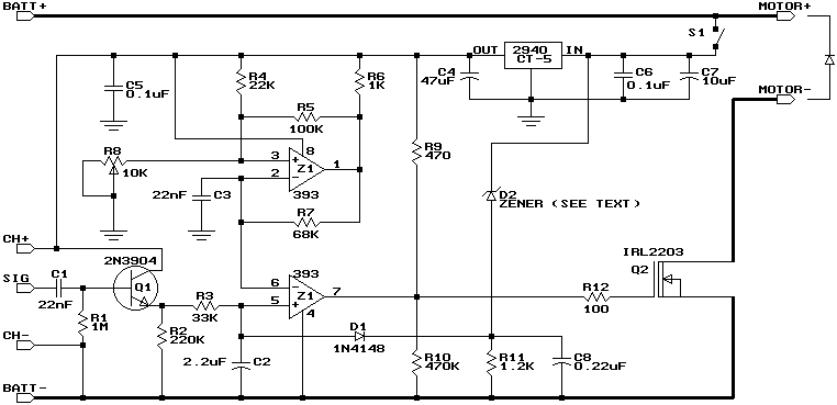
This design is based on one published by Milan Lulic in the German magazine elektroModell. Mr. Lulic's design is for surface mount technology (SMT) construction, whereas mine uses standard off-the-shelf components, and is therefore better suited to construction by...
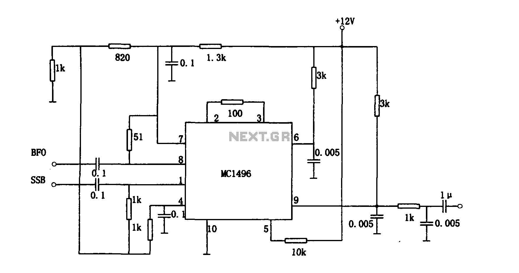
The provided information pertains to a detector circuit designed for multiplication. This circuit functions as a single-sideband amplitude modulation (SSB AM) signal detector, utilizing its principles to demodulate the received single-sideband signal and recover the transmitted signal. It employs...
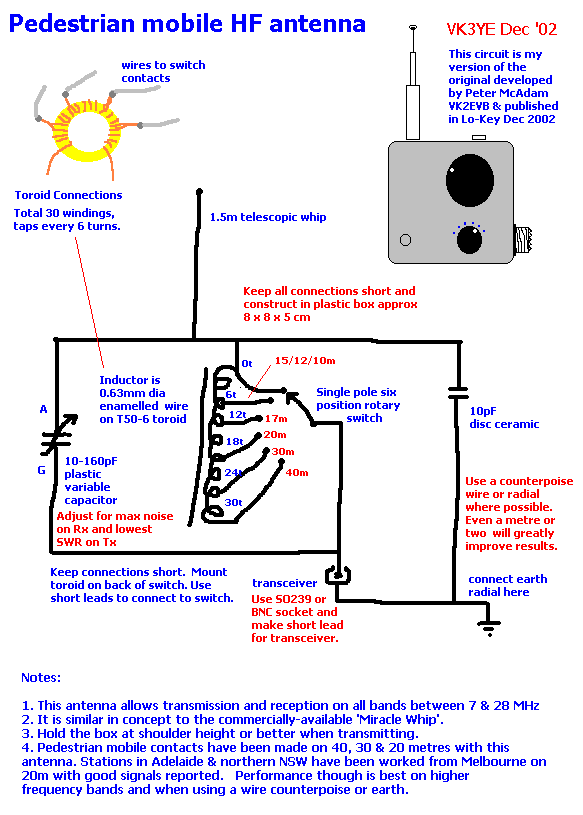
This document presents plans for a simple ground plane antenna that is effective in the FM band (88-108 MHz). It is constructed from a small plastic disk. The 6 x 6 loop antenna, designed by Graham Maynard, is highlighted...
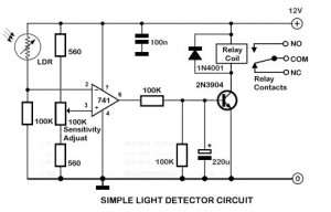
An ambient light sensor circuit is a circuit that utilizes light intensity to perform various applications. An ambient light sensor circuit typically consists of a light-dependent resistor (LDR) or phototransistor that detects the intensity of ambient light. The sensor converts...
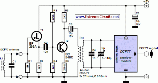
A popular project among microcontroller enthusiasts is to build a radio-controlled clock. Tiny receiver boards are available, equipped with a pre-tuned ferrite antenna that receives and demodulates the DCF77 time signal broadcast from Mainflingen in Germany. DCF77 has an...
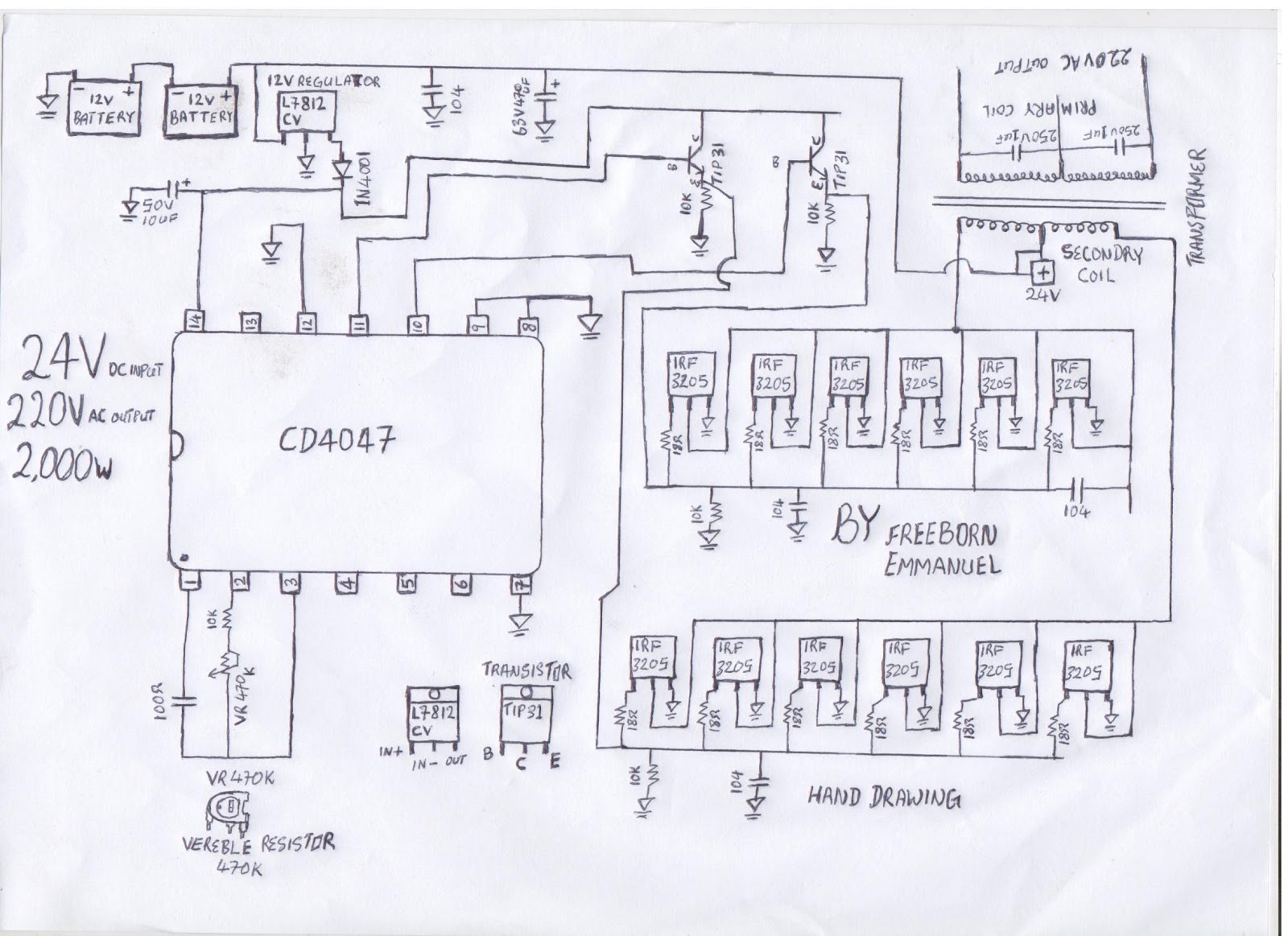
The diagram illustrates a modified square wave inverter circuit. By adjusting the frequency resistor (VR 470k), the inverter's output frequency can be optimized to effectively power a freezer compressor and various other electronic appliances in a living room. The...