
avr Programming an ATmega1284p with Arduino IDE and internal RC Oscillator
The ATmega1284P microcontroller is a versatile device commonly used in embedded systems. Programming this microcontroller involves using the AVR Dragon programmer in conjunction with the Arduino IDE, which simplifies the development process through its user-friendly interface. The installation of the mighty1284p library allows the IDE to recognize the ATmega1284P and facilitates the selection of different clock speeds via the board manager.
The provided LED blink example serves as an introductory program for testing the setup. The code initializes pin 13 as an output and toggles the LED state with a one-second delay, demonstrating basic control over digital outputs. The use of the `pinMode()` function in the `setup()` routine is essential for configuring the pin as an output, while the `digitalWrite()` function in the `loop()` routine controls the LED state.
In the context of AVR programming, the configuration of fuses is critical as it determines the microcontroller's clock source and speed. Setting the fuses to utilize the internal RC oscillator and dividing the clock rate by 8 results in a 1MHz operational frequency. This configuration can lead to confusion if the expected performance is based on a higher clock rate, such as the default 16MHz.
The Arduino IDE's capability to recognize the Mighty 1284P boards at different clock rates enhances the development experience by allowing users to select the appropriate settings for their applications. The provided bootloader configurations ensure that the microcontroller can be programmed and reset correctly.
In summary, programming the ATmega1284P with the Arduino IDE and AVR Dragon involves understanding the microcontroller's fuse settings, selecting the appropriate board configurations, and writing sketches that leverage the capabilities of the device. The successful execution of the LED blink program confirms that the setup is functioning correctly, paving the way for more complex applications.Program an ATmega1284p with my AVR Dragon and the Arduino IDE. So far I have installed mighty1284p, after writing my sketch. I compile it using the Arduino IDE and then cd into the (temporary) directory the sketch is build in. It contains the. hex file, as seems logic. /* Blink Turns on an LED on for one second, then offfor one second, repeatedly. This example code is in the public domain. */ // Pin 13 has an LED connected on most Arduino boards. // give it a name: int led = 1; // the setup routine runs once when you press reset: void setup() { // initialize the digital pin as an output. pinMode(led, OUTPUT); } // the loop routine runs over and over again forever: void loop() { digitalWrite(led, HIGH); // turn the LED on (HIGH is the voltage level) delay(1000); // wait for a second digitalWrite(led, LOW); // turn the LED off by making the voltage LOW delay(1000); // wait for a second } #include
h> #include
Evey I should have been able to do that math in my head, the clockrate is now 1MHz. mighty1284p in it`s original settings want`s aclockrate of 16MHz, so everything was just sooo slow that I thought it didn`t work at all, when in fact it was just crawling. ############################################################## mighty_opt8. name=Mighty 1284p 8MHz using Optiboot mighty_opt8. upload. protocol=arduino mighty_opt8. upload. maximum_size=130048 mighty_opt8. upload. speed=115200 mighty_opt8. bootloader. low_fuses=0xff mighty_opt8. bootloader. high_fuses=0xde mighty_opt8. bootloader. extended_fuses=0xfd mighty_opt8. bootloader. path=optiboot mighty_opt8. bootloader. file=optiboot_atmega1284p. hex mighty_opt8. bootloader. unlock_bits=0x3F mighty_opt8. bootloader. lock_bits=0x0F mighty_opt8. build. mcu=atmega1284p mighty_opt8. build. f_cpu=8000000L #mighty_opt8. build. core=arduino:arduino mighty_opt8. build. core=standard mighty_opt8. build. variant=standard ############################################################## mighty_opt1. name=Mighty 1284p 1MHz using Optiboot mighty_opt1. upload. protocol=arduino mighty_opt1. upload. maximum_size=130048 mighty_opt1. upload. speed=115200 mighty_opt1. bootloader. low_fuses=0xff mighty_opt1. bootloader. high_fuses=0xde mighty_opt1. bootloader. extended_fuses=0xfd mighty_opt1. bootloader. path=optiboot mighty_opt1. bootloader. file=optiboot_atmega1284p. hex mighty_opt1. bootloader. unlock_bits=0x3F mighty_opt1. bootloader. lock_bits=0x0F mighty_opt1. build. mcu=atmega1284p mighty_opt1. build. f_cpu=1000000L #mighty_opt1. build. core=arduino:arduino mighty_opt1. build. core=standard mighty_opt1. build. variant=standard ############################################################## Now my Arduino IDE has new boards: Mighty 1284p 1MHz using Optiboot and Mighty 1284p 8MHz using Optiboot which addresses/uses/references the internally available clockspeeds.
I can`t do this in my head, nor do I knew much about this. But the interwebs help a poor man out here, too: yields the above. which I assumed would be correct for the above avrdude parameters, but for now the IDE keeps asking me for a port (as in /dev/tty. usbAF65de) which of course t 🔗 External reference
Related Circuits
How to handle digital input/output (I/O) in AVR microcontrollers is explained using basic programs and circuits to illuminate an LED, generate a stepper motor sequence, read a push-button switch, and implement key debouncing. The handling of digital I/O in AVR...
This circuit eliminates the traditional tungsten filament lamp amplitude regulator along with its associated time constant and linearity issues. Additionally, it addresses the reliability problems commonly found with lamps. The Wien Bridge oscillator is utilized, leveraging the fact that...

This circuit incorporates capacitors and diodes into a conventional transformer-based series regulator circuit to enhance its operational range. It ensures regulation under low line voltage conditions and can extract additional power from a standard plug-in power supply. The described circuit...
The LM231 and LM331 family of voltage-to-frequency converters are well-suited for use in simple, low-cost circuits for analog-to-digital conversion, precision frequency-to-voltage conversion, long-term integration, linear frequency modulation or demodulation, and various other functions. When utilized as a voltage-to-frequency converter,...
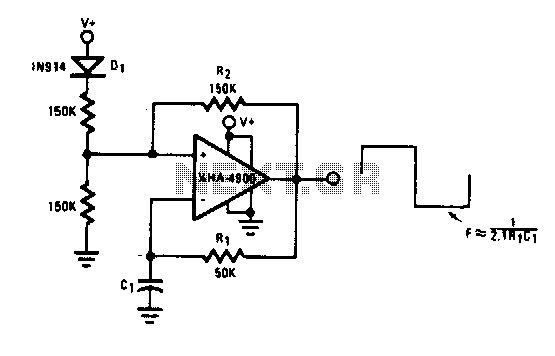
This self-starting fixed frequency oscillator circuit provides excellent frequency stability. R1 and C1 form the frequency-determining network, while R2 supplies regenerative feedback. Diode D1 improves stability by compensating for the difference between Voh and Vsupply. In applications requiring a...
Any vacuum-tube oscillator configuration has an equivalent transistor circuit. For example, consider the vacuum-tube oscillator, illustrated in Fig. 6-1 (A), which represents one form of Hartley oscillator. Positive feedback is accomplished by arranging the resonant tank E to be...