
How to handle digital input/output(I/O) in Avr Microcontroller
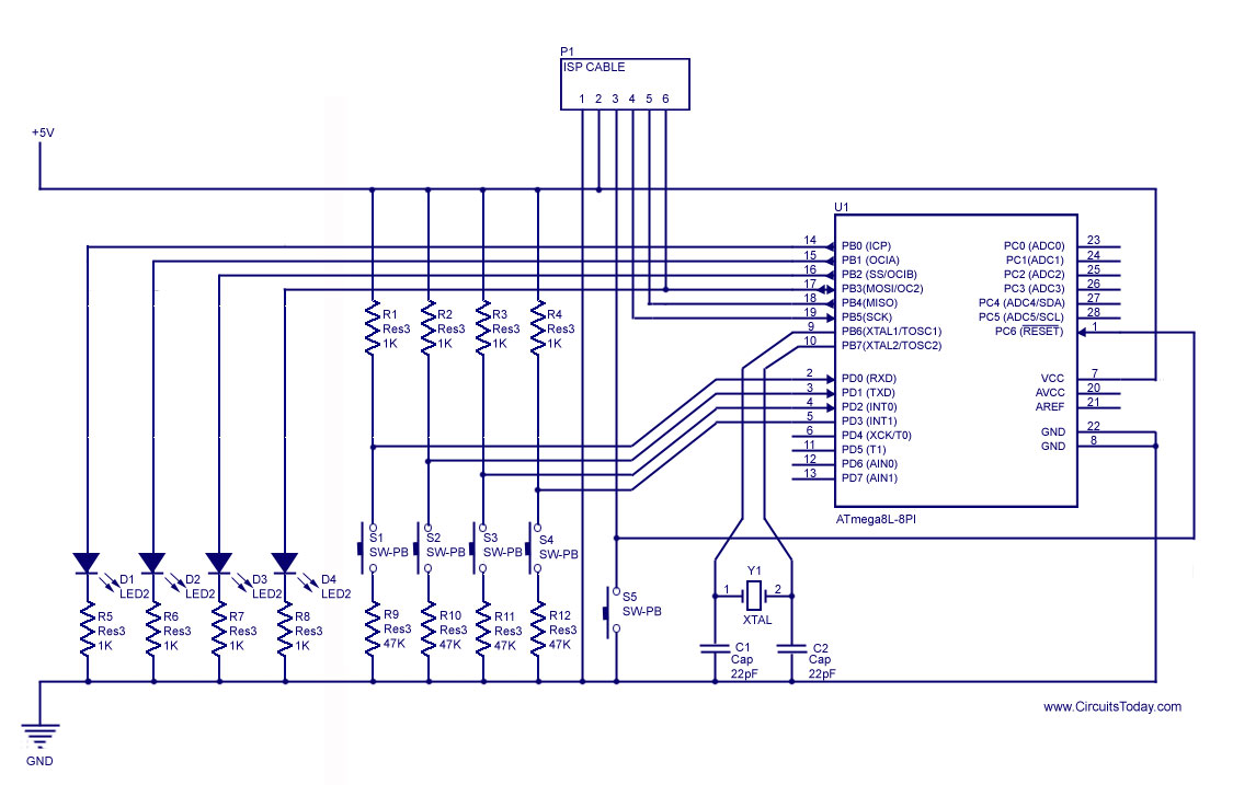
The handling of digital I/O in AVR microcontrollers involves configuring the microcontroller's pins as either input or output, allowing for interaction with external components such as LEDs, switches, and motors. The AVR microcontroller architecture typically provides several registers that control the direction and state of each pin.
To illuminate an LED, the relevant pin must be configured as an output. This is achieved by setting the corresponding bit in the Data Direction Register (DDR). For example, to turn on an LED connected to pin PB0 of PORTB, the program would set the DDRB register to configure PB0 as an output and then write a high logic level (1) to PORTB to turn on the LED.
For generating a stepper motor sequence, the microcontroller can be programmed to output specific sequences of high and low signals to the motor's control pins. This involves creating a timed loop that activates each control pin in the correct order, allowing for smooth rotation of the stepper motor.
Reading a push-button switch requires configuring the corresponding pin as an input. The microcontroller can then monitor the state of the pin, detecting whether the button is pressed (logic low) or released (logic high). To avoid erroneous readings due to mechanical bounce when the button is pressed or released, key debouncing techniques can be implemented. This can be achieved by introducing a delay or by using a state machine to ensure that the button state is stable before acting on the input.
In summary, the effective management of digital I/O in AVR microcontrollers is crucial for interacting with various electronic components. By using basic programming techniques and understanding the microcontroller's architecture, it is possible to create responsive and reliable electronic systems.How to handle digital input/output(I/O) in Avr Microcontroller? Explained using basic programs and circuit to glow an LED,generate stepper motor sequence,read push button switch and key debouncing.. 🔗 External reference
Related Circuits
A demonstration of external interrupts in the AVR (Atmega8) microcontroller, including a circuit diagram and C code for the interrupt service routine (ISR). The Atmega8 microcontroller is a versatile device widely used in embedded systems, particularly for applications requiring external...
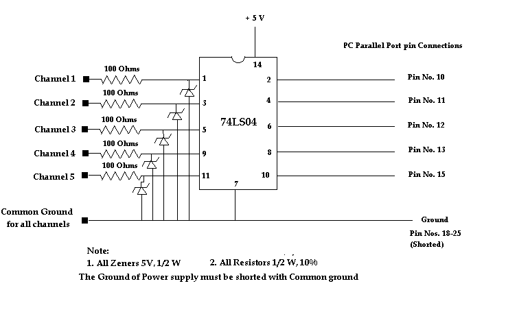
This is a simple circuit for a PC parallel port-based DLA. The circuit is primarily used to protect the port, which is integrated into the motherboard itself. The circuit design for a PC parallel port-based DLA (Data Line Adapter) focuses...
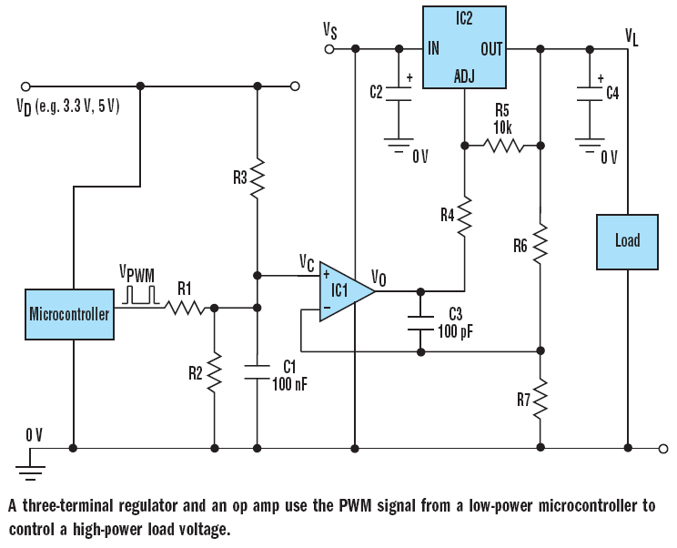
The filter consisting of resistors R1, R2, and capacitor C1 integrates the PWM waveform. The purpose of the operational amplifier appears to be that of a non-inverting amplifier, with the gain determined by resistors R6 and R7. However, the...
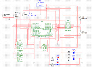
The objective of the project is to develop a robot capable of following a black line on a white sheet of paper and navigating through a maze constructed from these materials. The maze specifications include black lines with a...
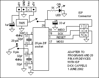
This adaptor lets me program 8 or 20 pin DIP devices using the In-System Programmer (ISP) described in Atmel's AVR910 application note. This circuit provides power and clocks for the part to be programmed and power to the ISP...
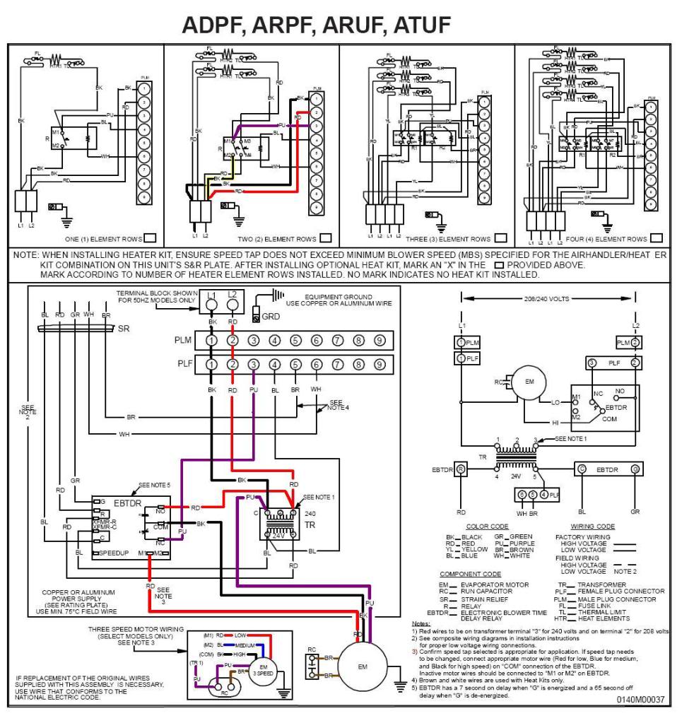
A Goodman Janitrol 2.5-ton Standard Air Handler, model #ARUF030-00A-1, was diagnosed with a malfunction where the fan could only be turned off by either switching off the breaker or disconnecting the black wire leading from the fan to the...