
Temperature Controller
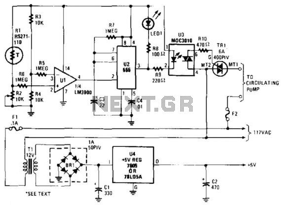
The described circuit utilizes a Wheatstone bridge configuration to monitor temperature changes via a thermistor (R1). In this setup, the thermistor's resistance varies with temperature, altering the voltage across the bridge. The reference resistor (R2) provides a stable comparison point, allowing the comparator (U1) to detect when the thermistor's resistance falls below or exceeds a predetermined threshold.
When the comparator (U1) detects a significant change in the thermistor's resistance, its output transitions to a high state. This transition activates the subsequent stage of the circuit, which is a delay timer (U2). The delay timer is set to approximately 25 seconds, providing a buffer period before subsequent actions are taken. Notably, after a 15-second interval, an LED (LED1) is illuminated, serving as a visual indicator that the system is in an active state.
Following the LED indication, another component (U3) is actuated, which likely controls the power delivery to the triac (TR1). The triac serves as a solid-state relay, allowing for the control of higher voltage and current loads, such as the hot water pump. When TR1 is triggered, it completes the circuit for the hot water pump, enabling it to operate and circulate water, thus facilitating the heating process in conjunction with the hot water heater.
This system exemplifies a practical application of temperature sensing and control in an automated hot water heating system, demonstrating the integration of analog and digital components to achieve reliable operation. The design ensures that the water heating process is initiated only when necessary, promoting energy efficiency and user convenience. A thermistor (RI) is compared with a reference (R2) in a Wheatstone-bridge circuit. Comparator Ul"s output goes high , which triggers U2. U2 is a delay of about 25 s. After 15 s, LED1 lights, U3 actuates, triac TRl triggers, and turns on a hot water pump. This system was used with a hot-water heater. 🔗 External reference
Related Circuits
A PIR sensor is triggered when using a timer to wait for 2 seconds after the sensor is activated. Without the timer, the sensor operates as intended. The PIR sensor is connected to an ATMega328p microcontroller, which has three...
Diode D1 and resistor R1 provide VDD isolation during the programming of 24-pin devices. The jumper J3 must be shorted for 24-pin device programming and left open for 28-pin device programming. The following EEPROMs are pin-compatible with their EPROM...
This circuit provides an explanation of the Phase-Locked Loop (PLL) controller unit for an FM transmitter. It is crucial for maintaining a digitally controlled and stable transmitter frequency. The core component of this unit is a PIC processor, specifically...
This integrated circuit is highly efficient and does not require any external glue logic for operation. It features two pins to control a motor: one for direction and the other for stepping pulse triggers. The design is compact and...
The circuit is constructed using two 555 timer integrated circuits, designated as U1 and U2. U1 is configured as a variable duty cycle oscillator with a fixed time period of approximately 0.1 seconds. The duty cycle can be adjusted...
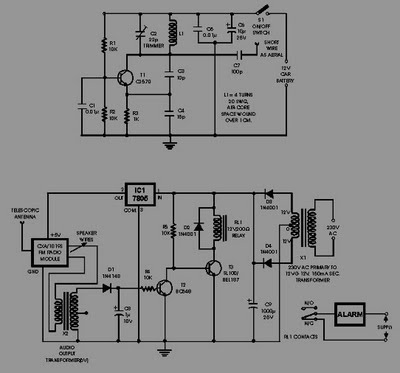
This circuit of an FM radio-controlled anti-theft alarm can be utilized with any vehicle that has a 6 to 12-volt DC supply system. The mini VHF FM transmitter is installed in the vehicle during the night when it is...