
LM4904 audio input differential amplifier circuit

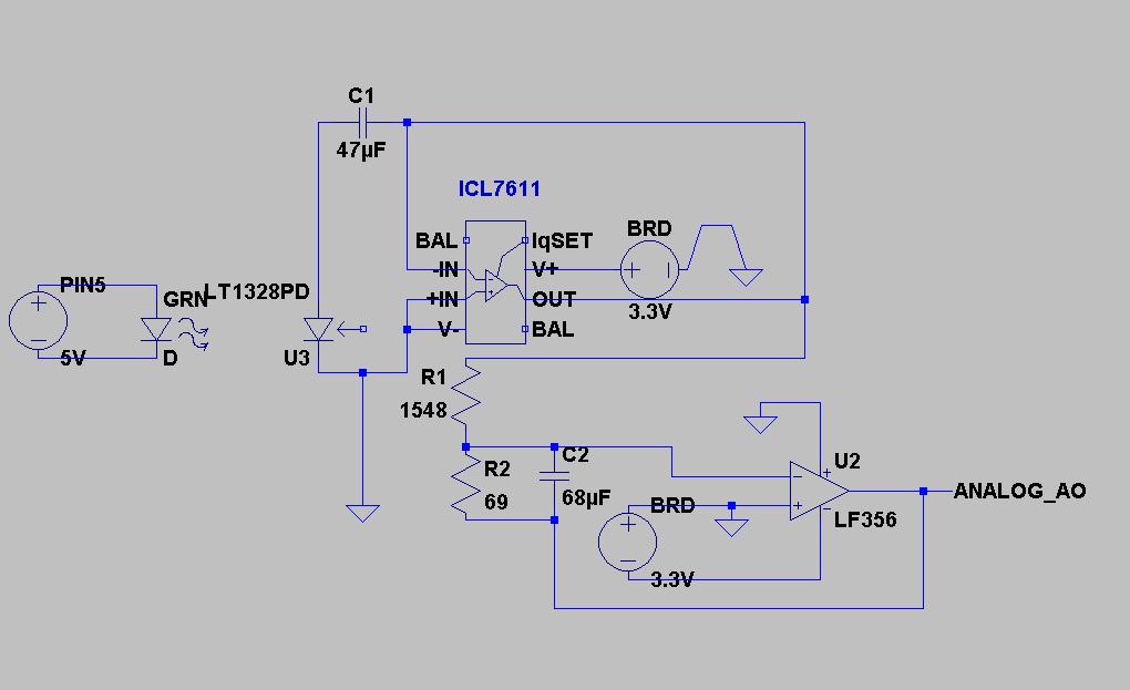
The LM4904 is a low-power audio input differential amplifier designed for high-performance audio applications. This circuit configuration is ideal for amplifying audio signals while rejecting common-mode noise, which is particularly important in environments with electromagnetic interference.
In this circuit, the audio input is connected to the +IN and -IN terminals of the LM4904. The differential input allows the amplifier to process the audio signal effectively by comparing the voltage levels at these two terminals. The output of the amplifier is a single-ended signal that represents the difference between the two input signals, amplified by the gain set by external resistors.
The circuit typically includes additional components such as capacitors for filtering and stability, as well as resistors to set the gain of the amplifier. The gain can be adjusted based on the application requirements, allowing for versatility in different audio systems. Power supply decoupling capacitors are also recommended to ensure stable operation and minimize noise.
Overall, the LM4904 differential amplifier circuit is a robust solution for audio input applications, enhancing signal integrity and providing high-quality audio output. Proper layout and component selection are crucial for achieving optimal performance in real-world implementations.Shown for the LM4904 audio input differential amplifier circuit. The audio signal in the form of a differential input to the terminal + IN and -IN terminals.
Related Circuits
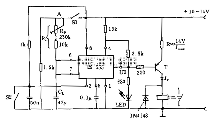
The circuit for the photoelectric switch S1 functions as a control switch for the luggage room light. In its closed operating state, the voltage is positive. If S2 is closed, irrespective of the state of S1, the output terminal...
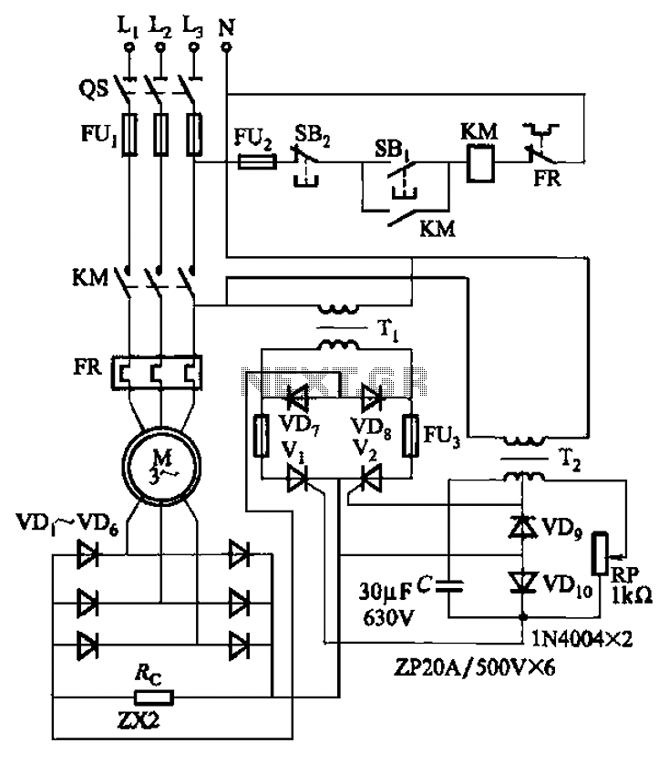
The circuit depicted in Figure 3-171 includes an auxiliary power supply that operates on single-phase AC power. It features a single-phase half-wave controlled bridge composed of diodes VD7, VD8, and thyristors V1, V2. The output current is managed by...
Craftsman Garage Door Opener Schematic and Installation Manuals. Sears Craftsman Garage Door Opener Parts. With 15 years in the business, Garage Door Openers Superstore is a leading provider. The schematic for the Craftsman Garage Door Opener provides a comprehensive overview...
The code implementation discussed in the previous post has been initiated. To improve organization, the code has been modularized into functions, simplifying the overall structure. It is available along with the other code. Challenges were encountered in calculating averages...
This emergency LED light is simple, inexpensive, and easy to build. The circuit connects to the battery, activating when the main power source is unavailable, such as during brownouts. White LEDs turn on automatically. Initially, the output voltage from...
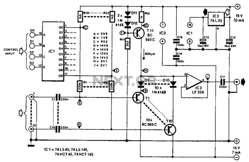
This circuit employs switched emitter followers instead of conventional analog switch CMOS chips, resulting in a more effective reduction of crosstalk between channels. It can manage up to 4 Vms with less than -80 dB crosstalk. The circuit design utilizes...