
BALLEST CIRCUIT DIAGRAM AND DESIGN DETAILS
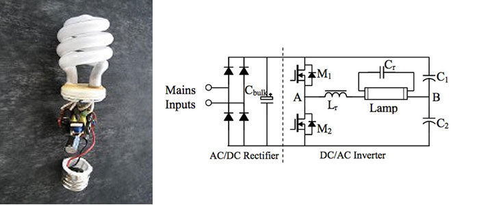
An electronic ballast is a device used to regulate the current to fluorescent lamps and provide sufficient voltage to start the lamps. The design of a transistor-based electronic ballast for a 40W, 230V fluorescent lamp involves several critical steps, including component selection, circuit design, and implementation.
1. **Component Selection**: The first step in designing an electronic ballast is selecting appropriate components. Key components include:
- **Transistors**: Power MOSFETs or IGBTs are typically used for switching. The choice depends on the desired efficiency and switching speed.
- **Inductor**: An inductor is used to limit the current and provide the necessary ballast function.
- **Capacitors**: These are used for filtering and stabilizing the voltage.
- **Diodes**: Fast recovery diodes may be included for rectification purposes.
- **Resistors**: Used for current sensing and feedback control.
2. **Circuit Design**: The circuit design process involves creating a schematic that integrates the selected components. The following elements should be included:
- **Input Stage**: This stage includes a rectifier circuit to convert the AC voltage (230V) to a suitable DC voltage for the transistors.
- **Oscillator Circuit**: A high-frequency oscillator is required to drive the transistors. This can be achieved using a feedback loop to ensure stable operation.
- **Output Stage**: The output stage includes the inductor and capacitors, which work together to provide the necessary voltage and current to the fluorescent lamp.
3. **Simulation**: Prior to physical implementation, the circuit should be simulated using electronic design automation (EDA) software. This step helps in verifying the functionality of the circuit and allows for adjustments to be made before actual construction.
4. **Prototype Development**: After successful simulation, a prototype of the electronic ballast can be built on a breadboard or PCB. This prototype should be tested for performance under various conditions to ensure reliability and efficiency.
5. **Testing and Optimization**: The final step involves rigorous testing of the prototype. Measurements should be taken for input current, output voltage, and the operating frequency. Adjustments may be necessary to optimize performance and ensure compliance with safety standards.
The design of a transistor-based electronic ballast for a 40W, 230V fluorescent lamp requires careful consideration of each component and stage to ensure efficient and reliable operation.I need a circuit diagram for electronic ballast (40w,230v) transistor based circuit diagram. What are the steps taken to design a electronic ballast?.. 🔗 External reference
Related Circuits

The schematic includes programmable AVRs. For other members of the AVR family or additional programmable ICs compatible with Ponyprog, there is a J1 connector (CON10) that facilitates hardware expansion of the programmer. Additional information about compatible ICs can be...
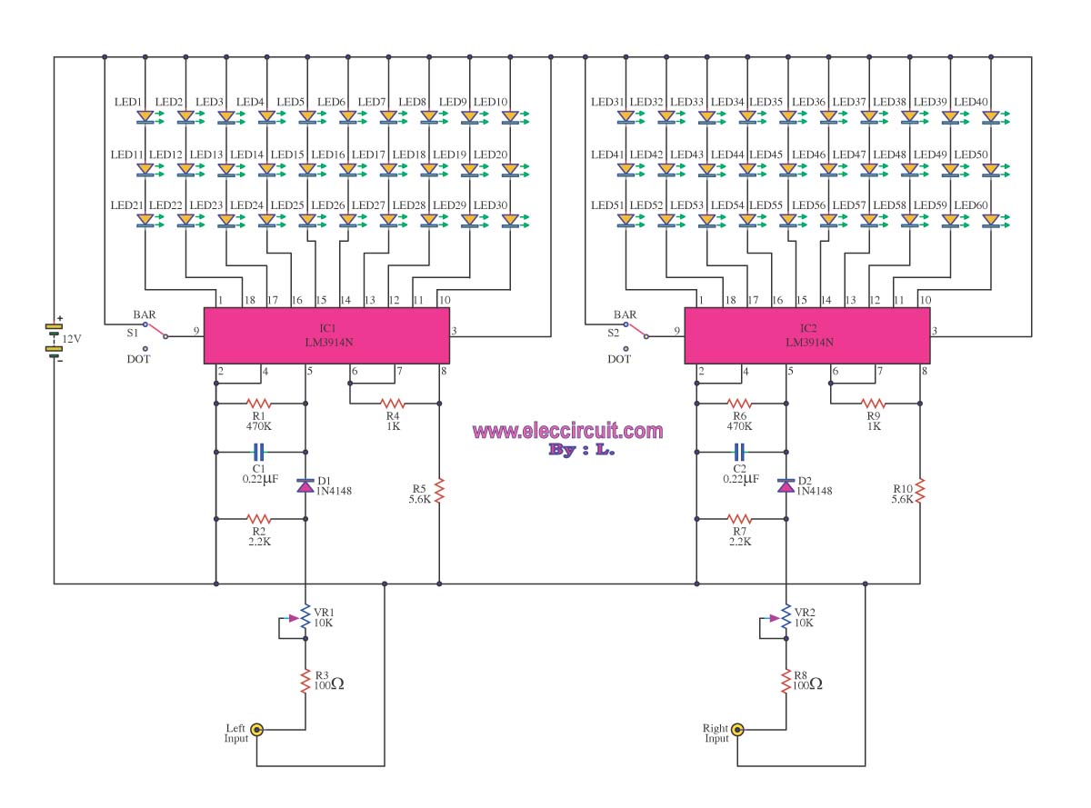
A VU meter is utilized to display the power level of audio signals and also serves as an aesthetic element. When purchasing a VU meter kit from an electronics store, options include assembling various parts independently or selecting a...
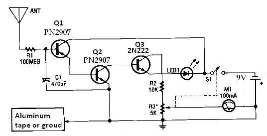
This ion detector circuit is designed to sense static charges and free ions present in the air. It is capable of detecting the presence of free ions, static electricity, or high voltage leakage. The project utilizes a short whip...
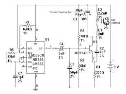
The team is highly interested in the design of a jammer circuit and has begun working on it. However, they are experiencing issues with the circuit, specifically that the signal is not being jammed effectively. The design of a jammer...
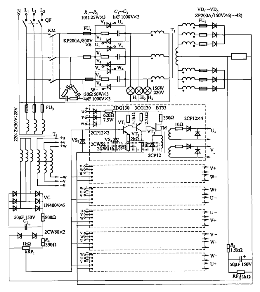
A three-phase thyristor power regulator circuit designed for plating applications, capable of handling currents from 1200A to 6000A at a voltage of 10V. The circuit comprises a main circuit, a trigger circuit, synchronous power components, and a voltage negative...

A simple touch dimmer circuit diagram using the TT6061 IC, which is a touch control integrated circuit used for light dimmer circuits and lamp dimmer circuits. The touch dimmer circuit utilizing the TT6061 IC is designed to provide a user-friendly...