
Jammer Circuit Using 555 Timer

The design of a jammer circuit typically involves generating a signal that interferes with the communication of other devices. To create an effective jammer, it is essential to understand the frequency of the signals that need to be disrupted. The circuit generally includes a signal generator, an amplifier, and an antenna.
The signal generator can be a simple oscillator circuit, such as a 555 timer configured in astable mode, or a more complex microcontroller-based setup that can produce a range of frequencies. The oscillator output should match or be close to the frequency of the target signals to ensure effective jamming.
An amplification stage is crucial for boosting the signal produced by the generator. This can be achieved using RF amplifiers, which are designed to operate at the specific frequencies of interest. The choice of amplifier will depend on the desired output power and the characteristics of the antenna.
The antenna is responsible for transmitting the jamming signal. It is important to select an antenna that is resonant at the target frequency to maximize the efficiency of the jamming signal. Common types of antennas used in jamming applications include dipole antennas and monopole antennas.
In troubleshooting the existing circuit, several factors should be examined. It is vital to ensure that the signal generator is functioning correctly and producing the intended frequency. Additionally, the output from the amplifier must be checked to verify that it is sufficiently powerful for effective transmission. Finally, the antenna should be inspected for proper connections and orientation, as these can significantly impact the performance of the jamming circuit.
Overall, designing a jammer circuit requires careful consideration of the components and their interactions to achieve the desired outcome.sir, we are very much interested in design of jammer circuit, even we started working on it but there is some problem with our circuit i.e signal is not getting jamm.. 🔗 External reference
Related Circuits
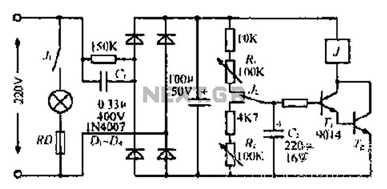
220V mains electricity is sent through a 0.33 µF capacitor (Ci) and a 50 kΩ resistive drop. A bridge rectifier composed of diodes D1 to D4 converts the AC voltage to DC. After passing through a 100 µF capacitor...

This circuit is designed to fill a header tank for a reticulated water supply on a farm. It serves eight troughs located in different paddocks, where a lack of water could have serious consequences for livestock. Previously, the tank...
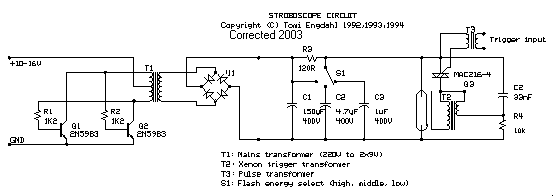
The stroboscope tube requires approximately 250-400V DC for operation. This high voltage is generated by a simple voltage step-up circuit constructed from transistors Q1, Q2, and transformer T1. This circuit outputs about 230V AC, which is then rectified by...

The circuit depicted in Figure 3-170 illustrates a wound rotor induction motor operating at various speeds, with a voltage (turn difference frequency EMF) U induced in the rotor. The rotor open circuit voltage is represented as Uo (Us0). A...
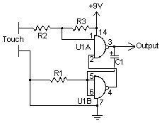
A touch switch is a switch that is turned on and off by touching a wire contact, instead of flicking a lever like a regular switch. Touch switches have no mechanical parts to wear out, so they last a...
Although it may lack the aesthetic appeal of traditional mercury barometers, which feature long glass tubes mounted on intricately carved and polished wood, the Torricelli barometer being discussed serves as a functional equivalent and electronic replica of the classic...