
Ion detector circuit diagram electronic project

This ion detector circuit operates on the principle of measuring ion concentration in the air, which can indicate the presence of static electricity or high voltage leakage. The short whip antenna serves as the primary sensing element, capturing free ions in the vicinity. The sensitivity of the circuit is adjustable via the resistor R3, allowing for fine-tuning based on the environmental conditions or specific detection requirements.
The micro-ammeter (M1), with a full-scale deflection of 100 mA, provides a visual representation of the ion concentration detected by the circuit. It is important to ensure that the meter is calibrated correctly to reflect accurate ion measurements. The configuration of the circuit is primarily focused on detecting negative ions; however, for applications requiring the detection of positive ions, the transistor configuration must be altered. This involves swapping the roles of PNP and NPN transistors, which changes the biasing conditions and allows the circuit to respond to positive ion charges.
The overall design is relatively straightforward, making it suitable for educational purposes or hobbyist projects. The simplicity of the circuit allows for easy troubleshooting and modifications, making it an excellent platform for understanding the principles of ion detection and static charge measurement. Care should be taken to ensure proper component ratings and connections to maintain circuit integrity and safety during operation.This ion detector circuit detects static charges and free ions in the air. This ion detector circuit can be used for detecting presence of free ions, static electricity or high voltage leakage. Antenna used in this project is a short whip antenna and the R3 resistor is used to adjust the sensitivity of the circuit.
The M1 from this circuit is a n 100mA micro-Ampere-meter. The detector is set up to detect negative ions. It can be made to detect positive ions by simply reversing the polarity of the transistors that comprise the circuit, i. e. , PNP units become NPN units, and NPN transistor is replaced by a PNP unit. 🔗 External reference
Related Circuits
This technique eliminates the need for an additional cable to power the FM antenna amplifier. The RF signal and the DC current that supplies the amplifier utilize the same cable simultaneously. An FM antenna booster circuit diagram can be...
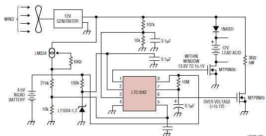
This simple wind charger circuit project is designed using the LTC1042 monolithic CMOS window comparator, manufactured by Linear Technology. The wind charger circuit utilizes wind power to generate the energy necessary for charging Ni-Cd or lead-acid batteries. When the...
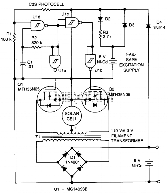
The circuit charges a 9-V battery at approximately 30 mA per input ampere at 0.4 V. U1, a quad Schmitt trigger, operates as an astable multivibrator to drive push-pull MOSFET devices Q1 and Q2. Power for U1 is derived...
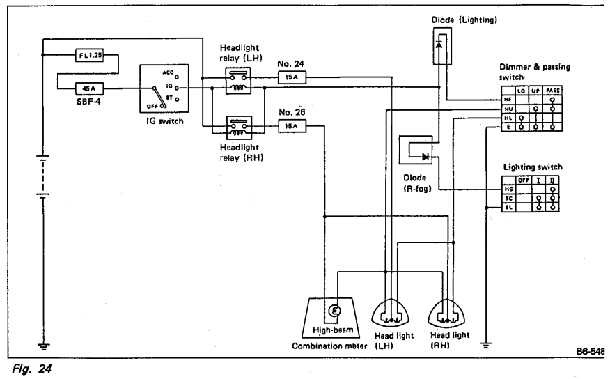
Understanding the headlight wiring in a car involves examining the purpose of two diodes in the circuit diagram. The circuit allows for two independent methods of activating the light relays: through the light switch or by flashing the high...
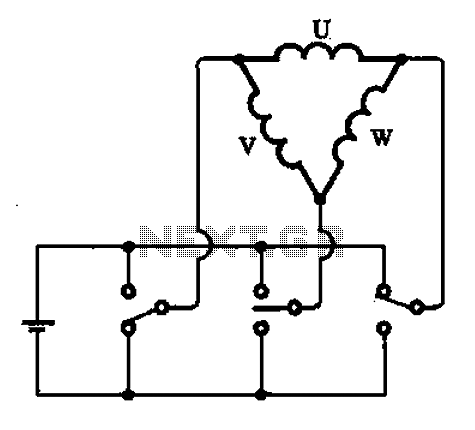
A stator coil connection illustrates the structure and connections of the stator coil. Figure (A) depicts a triangular connection, while Figure (B) illustrates a star connection, presented in two forms. The stator coil is a critical component in electric machines,...
This is an economical 150 Watt amplifier circuit that utilizes two complementary Darlington power transistors, TIP 142 and TIP 147. It is capable of delivering a robust 150 W RMS to a 4 Ohm speaker, offering significant audio output....