
Undervoltage-overvoltage indicator

The circuit utilizes Zener diodes to establish reference voltage levels, which are critical for monitoring voltage thresholds. The Zener diodes, D1 and D2, are selected based on the desired voltage levels at which the LED should be activated. When the input voltage falls below the voltage set by D1, the LED will turn on, indicating that the monitored voltage is below the acceptable range. Similarly, if the voltage falls below the level set by D2, the LED will also illuminate, providing a visual alert.
The configuration typically includes a voltage divider circuit that feeds the monitored voltage to the Zener diodes. The Zener diodes are connected in reverse bias mode, allowing them to conduct when the voltage exceeds their breakdown voltage. This conduction can be used to trigger a transistor or a relay, which in turn activates the LED.
In practical applications, it is essential to choose Zener diodes with appropriate power ratings to handle the expected voltage and current levels in the circuit. Additionally, resistors may be included in series with the LED to limit the current and prevent damage to the LED. The entire arrangement should be designed with consideration for the maximum expected input voltage and the operating environment to ensure reliability and longevity of the components involved.
Overall, this circuit serves as a simple yet effective voltage monitoring solution, providing immediate feedback through LED illumination when voltage levels fall below predetermined thresholds.This circuit will make the appropriate or above the value determined by zener diodes LED glow if the monitored voltage goes below Dl and D2.
Related Circuits
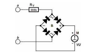
Using an old moving coil instrument, it is quite easy to create a simple voltmeter that visually indicates the status of a telephone. A simple voltmeter can be constructed using an old moving coil instrument, which is a type of...
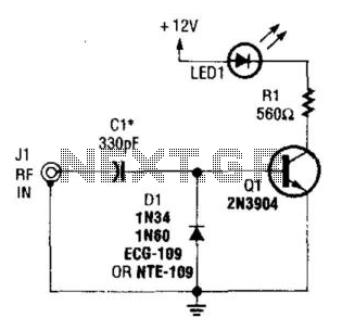
A simple RF detector circuit utilizing a visual indicator can serve as an RF output indicator. This circuit was designed for use as a transmitter ON indicator. The RF detector circuit typically consists of a few key components: a diode,...
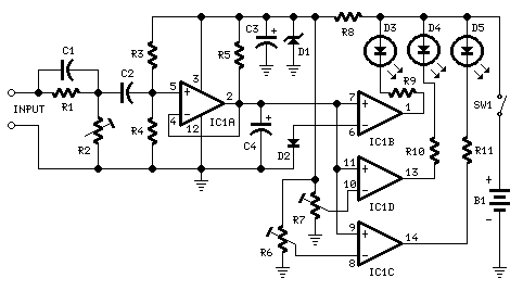
This circuit is intended to indicate the power output level of any audio amplifier. It is simple, portable, and displays three power levels that can be set to any desired value. IC1A is the input buffer, feeding 3 voltage...
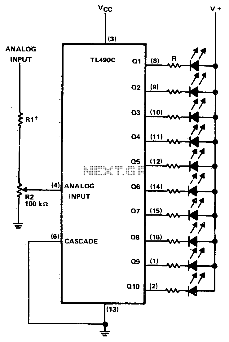
This ten-step adjustable analog level detector is capable of sinking up to 40 milliamperes at each output. The voltage range at the input pin should range from 0 to 2 volts. Circuits of this type are useful as liquid-level...
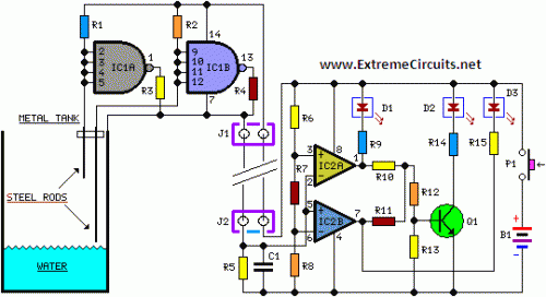
The entire project was developed at the request of a friend. Its purpose is to remotely monitor the water level in a metal tank located in the attic using a simple control unit placed in the kitchen, several floors...
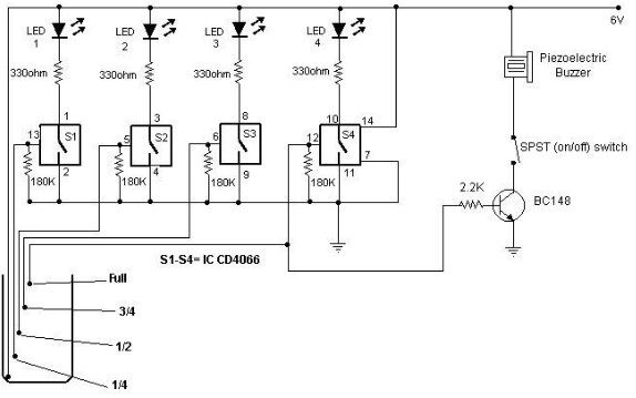
A low-cost water level indicator circuit can be designed using this schematic. This water level indicator utilizes a CMOS IC, the CD4066, to indicate the amount of water present in an overhead tank and provides an alarm when the...