
Supply Voltage Indicator
The circuit employs a simple yet effective design to monitor supply voltage levels through visual indicators. The primary components include two light-emitting diodes (LED1 and LED2), two resistors (R1 and R4), and two NPN transistors (T1 and T2). LED1 serves as the primary indicator for voltage levels below 12 volts, providing a clear visual cue through steady illumination or blinking to represent the decreasing voltage. The blinking frequency of LED1 acts as an intuitive gauge for the user, allowing for quick assessment of the supply voltage status.
Transistor T1 operates in a unique manner when subjected to inverse bias; it can generate oscillations within a specific voltage range. This behavior is leveraged to create a relaxation oscillator, which is an essential aspect of the circuit. The oscillation frequency is directly related to the input voltage, providing a dynamic response to voltage changes. The use of the BC337-40 transistor is particularly effective due to its capability to initiate oscillations at lower voltages compared to other NPN transistors, making it suitable for this application.
The circuit's design allows for easy adjustment of voltage thresholds through the selection of resistor values. By modifying R1 and R4, the user can customize the voltage levels at which LED1 and LED2 respond, tailoring the circuit to specific requirements. This flexibility makes the circuit versatile for various applications where monitoring supply voltage is critical.
In summary, this circuit serves as a reliable and straightforward method for visualizing supply voltage levels, incorporating adjustable thresholds and utilizing the unique characteristics of NPN transistors to provide real-time feedback on voltage status. The combination of steady and blinking LED indicators, along with the ability to adjust voltage sensitivity, makes this circuit an effective tool for monitoring electrical devices.This simple and slightly odd circuit can clearly show the level of the supply voltage (in a larger device): as long as the indicator has good 12 volts at its input, LED1 gives steady, uninterrupted (for the naked eye) yellow light. If the input voltage falls below 11 V, LED1 will start to blink and the blinking will just get slower and slower if t
he voltage drops further - giving very clear and intuitive representation of the supplys status. The blinking will stop and LED1 will finally go out at a little below 9 volts. On the other hand, if the input voltage rises to 13 V, LED2 will start to glow, getting at almost full power at 14 V. The characteristic voltages can be adjusted primarily by adjusting the values of R1 and R4. The base-emitter diode of T2 basically just stands in for a zener diode. The emitter-collector path of T1 is inversely polarized and if the input voltage is high enough - T1 will cause oscillations and the frequency will be proportional to the input voltage.
The relaxation oscillator ceases cycling when the input voltage gets so low that it no longer can cause breakdown along the emitter-collector path. Not all small NPN transistors show this kind of behavior when inversely polarized in a similar manner, but many do.
BC337-40 can start oscillations at a relatively low voltage, other types generally require a volt or two more. If experimenting, be careful not to punch a hole through the device under test: they oscillate at 9-12 V or not at all.
🔗 External reference
Related Circuits
The purpose of a DC power supply is to deliver the necessary level of DC power to a load by utilizing an AC supply at the input. Various applications demand different specifications; however, contemporary DC power supplies often ensure...
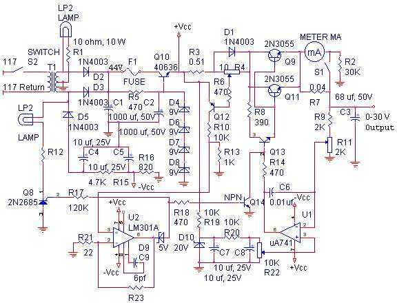
With reference to the schematic, lamp LP2 is a power-on indicator. The other lamp (lower) lights when the unit reaches its preset current limit. R5, C2, and Q10 (TO-3 case) operate as a capacitor multiplier. The 36-volt zener across...
This circuit utilizes a 13-volt zener diode, D2, which is responsible for voltage regulation. Approximately 0.7 volts are dropped across the base-emitter junction of the transistors, resulting in a higher current output of 12.3 volts. The circuit is capable...
A regulated voltage that can be adjusted to suit various applications is desired. This Adjustable Power Supply is compact, simple to construct, and can be modified to produce different output voltages. The Adjustable Power Supply circuit typically utilizes a linear...
This circuit is designed to power an AVR microcontroller from a 12V lead-acid battery. The watchdog component consumes only 14 µA. While integrated circuits (ICs) from manufacturers like Linear Technology or Maxim can be utilized for this purpose, they...
A switching power supply that has an output voltage significantly lower than its input voltage exhibits a unique characteristic: the current drawn from the supply is less than the output current. However, the input power (UI) is, naturally, greater...