
Bar-Mode Lights Sequencer

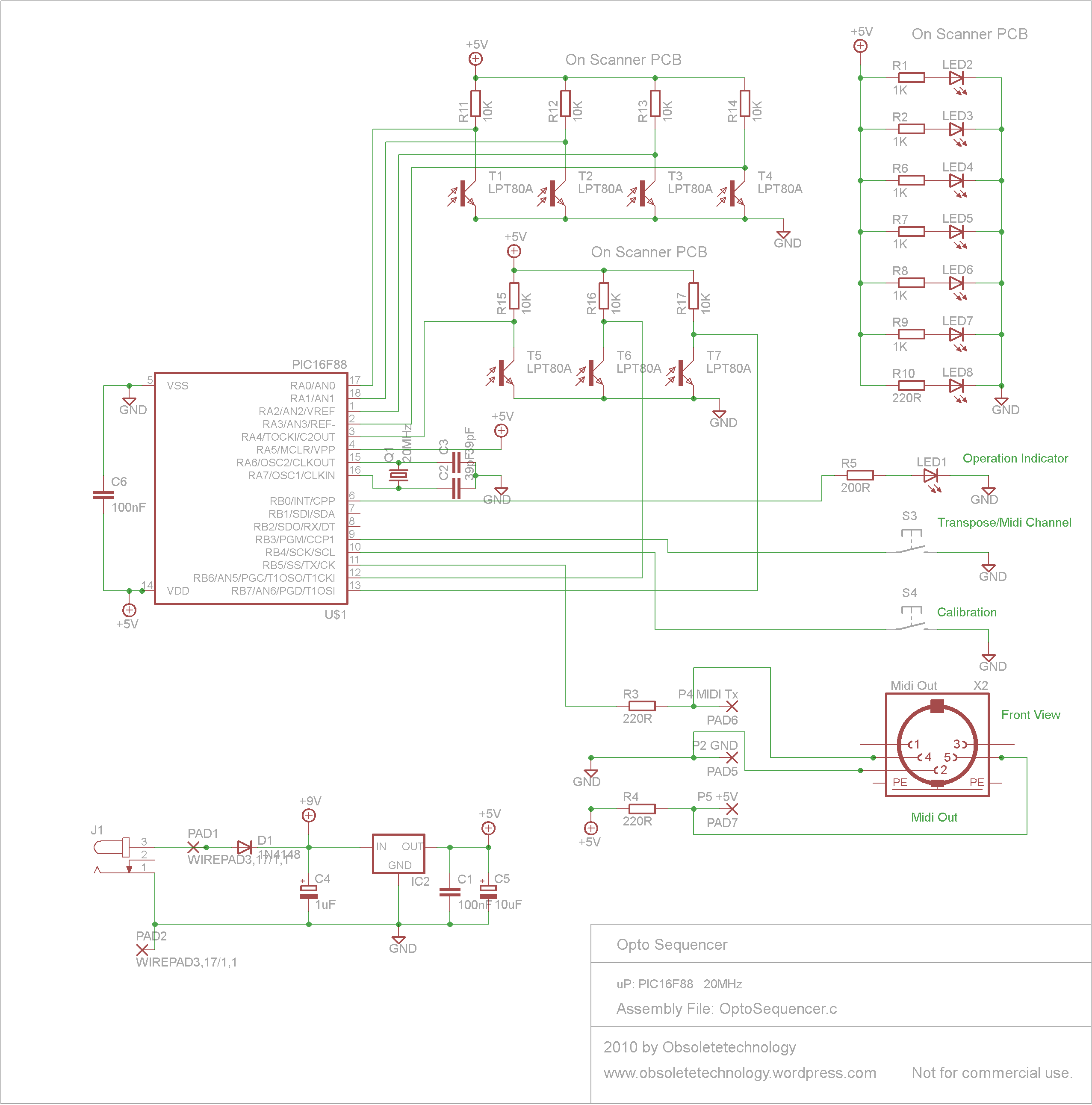
The circuit design involves connecting the terminal of resistor R7, which serves as a selection mechanism, to specific output pins of integrated circuits IC2 and IC3. This connection determines how many LEDs or LED clusters will be activated based on the selected output. When R7 is connected to pin #11 of IC2, it enables the control of seven outputs, effectively allowing the user to drive seven separate LEDs or clusters. The outputs are sequentially numbered, facilitating an organized approach to managing the connected components.
The cluster driver circuits, which can accommodate up to 15 configurations, are structured with two transistors and three resistors for each cluster. This arrangement allows for the effective management of power and signal distribution to the LEDs. The first eight clusters are driven by IC2, while IC3 handles the remaining clusters, thereby extending the capability of the circuit to manage a larger number of outputs.
In cases where only a single LED is required per output, the design can be simplified by substituting the cluster driver with a single transistor. This modification is exemplified in the circuit that includes diode D2, transistor Q3, and resistors R8 and R9. This streamlined approach reduces component count and complexity while still providing the necessary functionality for driving individual LEDs. The overall design is versatile, allowing for both cluster and single LED configurations based on user requirements.The terminal of R7 bearing an arrow must be connected to the desired output pin of IC2 or IC3 in order to select the number of LEDs or clusters forming the bar. For example: if you want to drive seven LEDs or clusters connect R7 to pin#11 of IC2 (Output 8) and the LED or cluster drivers to Outputs 1 to 7 respectively.
Up to 15 of these cluster dri ver circuits, each formed by the LEDs, two transistors and three resistors can be built and connected to the progressively numbered outputs of IC2 (the first eight clusters) and IC3 (the remaining clusters). Wanting to drive only one LED per output instead of a cluster, the above mentioned cluster driver can be substituted by a single transistor, as shown in the circuit formed by D2, Q3, R8 and R9.
🔗 External reference
Related Circuits

This simple circuit drives six LEDs in a "Knightrider scanner mode." Power consumption primarily depends on the type of LEDs used, particularly when utilizing a 7555 (the CMOS version of the 555 timer). The circuit is designed to create a...
The purpose of this circuit is to create a ring in which LEDs or lamps illuminate sequentially. Its main feature is high versatility; a loop containing any number of LEDs or lamps can be built, as each illuminating device...
This project has been contemplated since the first attendance at a concert by Institut für Feinmotorik, a German band known for their unconventional use of turntables to produce sound and noise. What was most striking about their performance, aside...
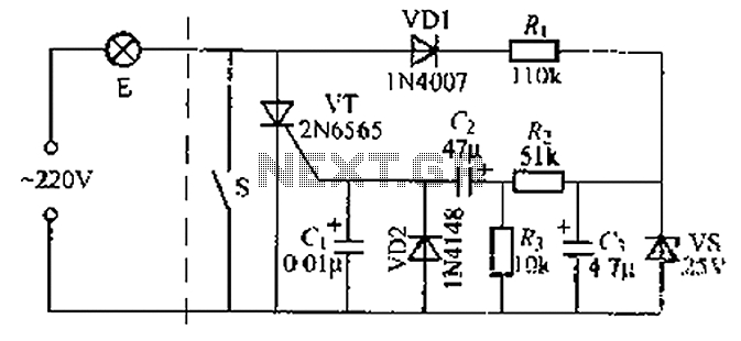
A delay circuit using an improved quenching lamp pull switch is described, focusing on its performance and the delay function in lighting control. The circuit exhibits a high degree of stability and reliability. When switch S is closed, the...

This circuit features a LED sequencer/chaser utilizing the CD4017 and NE555 integrated circuits (ICs). The CD4017 is a CMOS counter IC with 16 pins, providing 10 outputs based on the clock pulses received at its clock input, pin 14....
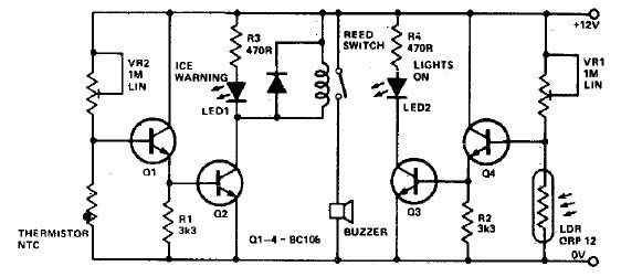
This electronic project circuit diagram for an ice warning and lights reminder system alerts drivers when their vehicle lights should be activated and warns them if the outside temperature approaches zero degrees Celsius. The system employs an LED indicator...