
Ice warning and lights reminder circuit diagram project
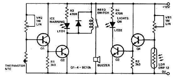
The ice warning and lights reminder circuit is designed to enhance driver safety by providing timely alerts regarding environmental conditions that may affect driving. The circuit integrates a thermistor to measure ambient temperature, which will trigger an alert when the temperature falls close to the freezing point. The LDR is used to detect ambient light levels, ensuring that the vehicle's lights are activated in low-light conditions, thus improving visibility and safety.
The core components of the circuit include the thermistor, LDR, variable resistors (VR1 and VR2), an LED indicator, a buzzer, and NPN transistors for signal amplification. The thermistor's resistance decreases as the temperature rises, allowing it to function as a temperature sensor. The LDR operates on the principle of resistance change with light intensity, providing input to determine when the vehicle's lights should be turned on.
The circuit design allows for easy calibration of both temperature and light sensitivity through the variable resistors. This feature is crucial, as it enables the user to tailor the system's responsiveness based on specific environmental conditions or personal preferences. The use of high-gain NPN transistors ensures that the signals from the thermistor and LDR are adequately amplified, allowing the LED and buzzer to activate reliably under varying conditions.
Proper housing for the thermistor and LDR is essential to protect these components from environmental factors that could affect their performance. This may involve using enclosures that shield them from moisture, dust, and physical damage while still allowing them to accurately sense temperature and light.
Overall, this circuit serves not only to remind drivers to activate their lights but also to prevent potential accidents caused by icy conditions, making it a valuable addition to vehicle safety systems.This ice warning and lights reminder electronic project circuit diagram will tell a driver if his lights should be on and will warn him if the outside temperature is nearing zero by lighting a LED and sounding a buzzer. Using the VR1 you can adjusts sensitivity for temperature and using VR2 you can adjust sensitivity for the light.
Both thermist or and LDR should be well protected. More high gain NPN transistors will work for this electronic project. 🔗 External reference
Related Circuits
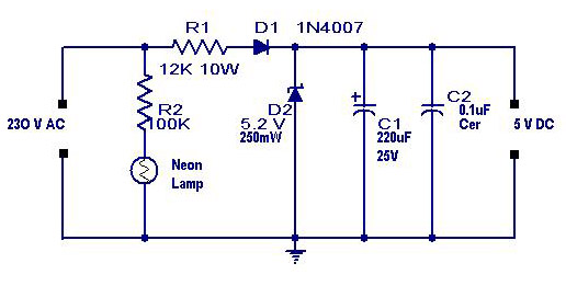
A simple transformerless power supply circuit with a diagram and schematics that provides a 5 volts DC output. This is a low-cost, low-current power supply circuit suitable for simple applications such as powering an LED. The transformerless power supply circuit...

The resulting timer circuit is made from a CD4060, includes an oscillator and a 14 stage binary counter, two CD4040's, which are 12 stage binary counters, a CD4012 Dual Nand gate and a CD4013 Dual D Latch. The CD4060...

To create a versatile and generic microcontroller board, the information provided thus far is sufficient. It covers the essential components needed to achieve this. The design of a microcontroller board requires careful consideration of various factors to ensure versatility and...

The circuit activates a light corresponding to the first button pressed in a "Who's First" game. Three stages are illustrated, but the circuit can be expanded to accommodate any number of buttons and lamps. The described circuit operates as a...
This document presents the circuit diagram of an IC-controlled emergency light with a charger, which functions as a 12V to 220V AC inverter circuit. The primary features of this circuit include automatic activation of the light during mains failure...

The transmitter operating at 2 meters (144 MHz) was primarily designed for use by radio amateurs as a radio beacon. It generates a high-quality signal suitable for this purpose. The 2-meter transmitter circuit typically includes several key components to ensure...