
Twin Bell Circuit Circuit

The circuit design described enables a single doorbell system to be activated by two separate buttons, enhancing user convenience and providing a clear indication of which button has been pressed. In this configuration, the primary button, S1, is connected directly to the doorbell, allowing for continuous ringing when activated. The secondary button, S2, is integrated into the circuit in such a way that it operates in conjunction with a relay (Rel) to produce a distinct ringing pattern.
When S2 is pressed, the voltage generated by the doorbell is directed through a rectifier diode (D1) to ensure that the voltage is unidirectional, thus protecting the circuit from potential damage due to reverse polarity. The output from D1 is then filtered by a smoothing capacitor (C1), which stabilizes the voltage and reduces fluctuations that could affect the operation of subsequent components.
The time constant of the circuit is determined by the resistor (R2) and capacitor (C2), where the equation t = R2C2 indicates the time it takes for the voltage across C2 to reach a threshold that activates the transistor (T1). Once T1 is energized, it activates the relay (Rel), which interrupts the circuit connected to S2, causing the bell to cease ringing. This interruption effectively creates a short burst of sound, distinguishing it from the continuous ringing produced by S1.
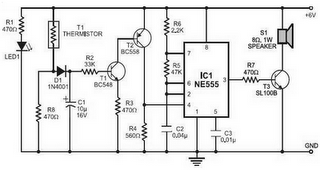
After a brief period, the capacitors C1 and C2 discharge, allowing the relay to return to its resting state. This reset enables the doorbell to be ready for the next activation, whether from S1 or S2. The design thus ensures that S1 provides a continuous alert while S2 serves as a short, distinct signal, allowing users to easily identify which button has been pressed without confusion. This dual-button system is particularly useful in larger properties where multiple entry points require a single doorbell solution. It is often desirable for a single doorbell to be operated by two buttons, for instance, one at the front door and the other at the back door. The additional button, S2 in series with the break contact of relay Rel, is connected in parallel with the original bell-push, SI.
When S2 is pressed, the bell voltage is rectified by D1 and smoothed by CI. After a time, t = R{R2C2, the direct voltage across C2 has risen to a level here T1 switches on. Relay Rel is then energized and its contact breaks the circuit of S2 so that the bell stops ringing. After a short time, CI and C2 are discharged, the relay returns to its quiescent state and the bell rings again. In this way, SI will cause the bell to ring continuously, wliile S2 makes it ring in short bursts, so that it is immediately clear which` button is pushed.
Related Circuits
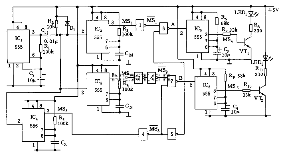
The capacitor filter operates by measuring the capacitance, which is proportional to the pulse width. This measurement is compared to a nominal capacitance to determine qualification. The circuit, as illustrated in the accompanying figure, includes IC1 along with resistors...
The circuit diagram is designed for precise control of DC motors. It converts DC voltage into a series of pulses, where the duration of each pulse... The circuit utilizes a pulse-width modulation (PWM) technique to regulate the speed and torque...
An infra-red or wireless remote control has the disadvantage that the small, handy, remote transmitter is often misplaced. The sound operated switch has the advantage that the transmitter is always with you. This project offers a way to control...
Fire alarm circuit using an LDR (Light Dependent Resistor) as a flame sensor. It warns the user about fire accidents by detecting smoke produced during a fire. As smoke passes between an LED and an LDR, the amount of...
The simplest polarity protection technique is to connect a series diode to the power line input. The diode conducts only when the power supply is connected correctly. A series diode is an effective method for preventing reverse polarity in electronic...
Prior to the test point, there is an AD744 operational amplifier with its output connected to a 10nF capacitor. Following this, a 1kΩ resistor connects to ground. From the junction where the capacitor and resistor meet, a 4.7kΩ resistor...