
Basement LEDs
The silicon button pad was placed on the soldered PCB, and connections were made according to the previously simulated button press circuit. Eight strands of colored wire were twisted together to assist in testing, using the position of colors in the rainbow as indicators for pin connections. Code adjustments were required to ensure the Arduino supplied voltage to the rows of the SparkFun pad and read from the columns. The assembly process followed the guideline of starting with components that are harder to reach if others are soldered first, typically working from the middle of the PCB outward. After soldering, component legs were clipped to maintain clarity. Each LED was tested before soldering, ensuring proper functionality and preventing damage. Distinct color variations in yellow LEDs were noted, raising concerns about consistency during operation. Soldering was performed alternately for LEDs and diodes, with verification of functionality after assembly.
A test circuit was developed to understand the operation of a small button matrix with shift registers and Arduino code. The Arduino processes button presses in the current column, generating a new byte for the parallel output register to activate the next row. Non-permanent connections to the PCB were sought for testing with actual buttons. The PC74HCT165P shift register was utilized instead of the previously used 7JE75K, linked to the same LED set. The issue of faintly glowing LEDs when they should be off was identified as a side effect of the lack of a latch pin in the PC74HCT165P, leading to immediate output pin activation during data shifting. Understanding the function of the shift registers in relation to button presses was aided by collaboration with an electronics-savvy individual. Future posts will include the schematic and annotated code, along with explanations of the code's functionality.In order that the MonomeSerial software `sees` the monome clone, it`s necessary to change the serial number of the arduino`s EEPROM to resemble the serial number of a real monome. I successfully followed Melka`s instructions that have been posted on the bricktable blog (update: the bricktable blog instructions have been updated, you should follow
those instructions rather than my version here). I installed the D2XX drivers on my winXP laptop first, following instructions in this PDF. This part requires you to have the arduino plugged into the PC via the usb cable. NB. while following these instructions the `found hardware wizard` will run twice, this is normal, just point it to the directory that contains the drivers you downloaded both times. There is 2 protocols described on the monome site, and the 64/128/256 seems to be more complete (15 message IDs, 9 for the 40h protocol), so maybe you`d better use m256-xxx I`ve been adjusting the MAX test code, to gets the lights moving in different ways.
While doing this I noticed that if a row is asked to light seven or eight of its LEDs at once, all the lights go out and I have to reset the arduino to get it going again. I`d like to find out why that is. The button pad PCBs are all soldered up and all the components are in place in the breadboard version of the controller.
To test that the MAX chip was working and wired up correctly, I uploaded this code to the arduino. The MAX7219 has `DIG` pins and `SEG` pins, corresponding to the two axes of the LED matrix. The SEG pins supply voltage to the grid, and the DIG pins act as ground sinks. The SEG pins are named A to G and the eighth pin is called SEG DP. The DP pin should come first in the sequence, not last (the way I wired it first). So I used a chisel and hammer. Which snapped them in the correct place, but a few times the casing to one of the sides of the break was damaged, sometimes losing a pin. Meanwhile, at Owen`s suggestion I`m twisting wires together like this as a way of attaching two of them to a single via hole in the button pad PCBs (one wire is a jumper connecting the PCB to another one, the second wire leads to one of the shift registers or the max LED driver chip).
The four black plastic things with female sockets are IDC connectors to attach to two ribbon cable lengths. I messed this up with the first one I tried and broke it, this time I`ll use a vice to push down the part that cuts the cable.
The IDC headers will plug into the paired header pin strips, forming a removable connection from the arduino shield PCB (at least I think I`ll use a shield) to the button pad. The things with pins are IC sockets. I`m using these so that I don`t have to solder the chips directly to the PCBs, and can replace them easily if necessary.
There are two 16 pin sockets for the shift registers, and one 24 pin socket for the max chip. A new section has been added to the bricktable blog which is designed to document the construction of a single colour, sparkfun+arduino monome clone, just like the one I`m building. So far there`s not much information there, but they have published the arduino code for their project, which is very useful.
Since this code takes care of a bunch of things I haven`t started to implement yet, like serial reading and writing, LED control and button debouncing, It`s likely that I`ll end up using it, or at least something derived from it. I`m not sure how to arrange that, mechanically, at the moment. Can anyone see how unsped has done it in this photo I can`t quite make out how he`s attaching two cables to single vias along the outside edges of the boards.
EDIT: Unsped explains that, for the edge vias which needed more than one wire attached to them, he first soldered male header pins in place, then soldered the necessary wires to those pins. Finally he covered the pins and the joints with liquid plumbers tape to prevent short-circuits. He adds that if he were to do the project again he wouldn`t use header pins, but instead solder one wire pushed through the hole, and then solder the second one onto the pad created by soldering the first.
I placed the silicon button pad ontop of the soldered-up PCB and hooked it up according to the circuit I`d made earlier in which I had simulated button presses using hookup wire. I twisted two cables together from eight strands of coloured wire to help with testing. I`m using a colour`s position in the sequence of hues that form a rainbow as an indicator of its index position so that I can see quickly whether I`m connecting to the correct pin.
I needed to alter the code a bit to get this working. Using the orientation of the silkscreen print on the PCB`s, the arduino needs to supply voltage to the rows of the sparkfun pad, and read from its columns, not the other way around. Many of the guides stress the importance of beginning with the components that would be hard to reach if others were already soldered in place.
In general this means working from the middle of the pcb outwards. As I progressed, I clipped the legs off each component after it`s solder had hardened, to keep things transparent. Before I attached each LED to the board, I tested that it worked by slotting it into one of the other boards that I had hooked some wires to from my breadboard (don`t forget to include a suitable resistor before the LED to prevent it from burning out).
Here`s a view of the underside of the PCB I used to test the LEDs. It seemed to make sense to connect the anode (+ side, longer leg) of the LEDs to the BLUE via, because this places them neatly in the middle of the button area without the need to bend their little legs. While testing the LEDs I noticed that there seemed to be distinct colours of yellow in the batch that I ordered.
Some LEDs shone a warm, orangy yellow and anothers a more lemony colour. I`m hoping the difference won`t be pronounced enough to be disturbing, or that perhaps when the LEDs are being driven by the MAX driver, their colour will be consistent. I soldered LEDs and diodes alternately, turning the PCB around as necessary while it was gripped by the pincers of the `helping hand`.
Here`s the middle section almost done. Once it was done I used some wires from the LED testing circuit on the breadboard to touch the joints of the LEDs again to verify that they still worked. One of them didn`t, I probably damaged it by applying the soldering iron for too long. Once the iron is fully heated it seems that about 2 seconds of contact with the joint before applying the solder was enough to get a good result.
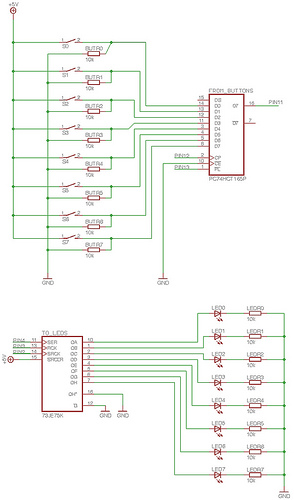
I removed the dead LED using solder wick to remove the solder while pulling the plastic dome gently with pliers. I ordered 70 LEDs, so I can afford 6 of them to be wasted. Using one of the spakfun pcb`s as a reference, I made a test to help understand the way a small button matrix would work with the shift registers and the arduino code.
Now that the arduino `knows` which buttons are pressed in the current column, it creates a new byte to send to the parallel out register, to active the next row in the sequence Here I`ve simulated pressing three buttons by making connections between the input (SWITCH) and the output (SWITCH-GND) sockets. Below you see the output of the serial window in the arduino software. Next I need to figure out how to connect these wires to the PCB in a non-permanent way so that I can test this circuit with the real buttons, and see if it`s still working as expected.
If anyone has any thoughts about how I could do that please post in the comments. I swapped the 7JE75K shift register I was using in a previous post for a PC74HCT165P (the monome uses a 164 too, for detecting button presses). To test it out I linked it to the same set of LEDs. When one of the `switches` was closed, the corresponding LED should light up. Once I got this working I noticed that whenever I had any LEDs th were on, the LEDs that supposed to be off were also glowing faintly (see image).
It turns out that this is a side effect of the PC74HCT164P having no latch pin. When it shifts data from one slot to the next, that data is also immediately sent to the output pins. A latch, like the one the 7JE75K has, makes it possible to shuffle the bits around in the register in `secret` and when they`re ready, they`re `revealed` to the output pins all at once.
So with the 165, when one bit in the register is high, it very briefly activates each of it`s output pins as that bit gets shifted. When this happens many times a second it looks like the LEDs are faintly glowing. I knew that these had something to do with dealing with button presses but I wanted to understand exactly what they were doing.
With the help of an electronics-savvy friend I set up an arduino circuit. In this post I`ll add the schematic and the code, and in the following post I`ll try to explain what the code is doing (though it`s heavily annotated, so that might be redundant). Click the images to see bigger versions. 🔗 External reference
Related Circuits
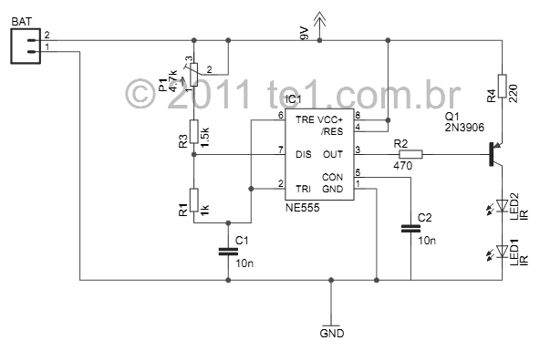
This small device is designed to jam remote controls by directing it at the TV. The circuit utilizes a 555 timer configured as an astable multivibrator, generating a frequency of approximately 38 kHz, which corresponds to the frequency at...

This circuit simulates the flashing lights of a police car, similar to those seen on British police vehicles. The operational amplifier IC1a functions as a square wave oscillator, with an adjustable frequency controlled by the variable resistor VR1 to...
The circuit below demonstrates how to power one or two LEDs from a 120-volt AC line. It utilizes a capacitor to reduce the voltage and a small resistor to limit the inrush current. As the capacitor needs to allow...

A dimming control circuit generates a dimming control signal to determine the brightness of at least one light-emitting diode. The dimming control signal consists of multiple bright-dark cycles, each comprising a bright phase and a dark phase. The bright...
The following are current regulator circuits that can be used to drive light emitting diodes. As always, take time to do some testing before attempting to use these circuits in actual applications. Current regulator circuits are essential for controlling the...
Recently, LED strips were purchased from a local electronics shop to replace spotlights in the kitchen. The chosen strips emit a cold white light, which is effective for nighttime illumination, resembling a moonlight hue. Operating at 12V, they consume...