
Mains supply fail Emergency Light
The circuit design consists of two main functional blocks: a charger power supply and a LED driver circuit. The charger power supply utilizes an LM317 adjustable voltage regulator (IC1), which is capable of providing a stable output voltage suitable for charging a 6V battery. The input AC voltage is reduced to a safe level using a transformer, which outputs 9V at 500mA. This voltage is subsequently rectified using a bridge rectifier made up of four IN4007 diodes, effectively converting the AC voltage to DC. The output of the rectifier is smoothed with a 25V/1000µF filter capacitor, which minimizes voltage ripples, ensuring a steady DC supply to the regulator.
The LM317 regulator receives this unregulated DC voltage at its input pin (pin 3) and, through the adjustment of a 2.2K potentiometer (VR1), allows for fine-tuning of the output voltage to meet the charging requirements of the battery. A 16-ohm resistor (R16) limits the charging current to prevent overcharging. When the battery voltage reaches approximately 6.8V, a zener diode is triggered, allowing the charging current to divert through a BC547 transistor (T1), thereby ceasing the charging process.
The LED driver section is designed to control a total of twelve 10mm white LEDs, which are connected in parallel, each accompanied by a 100-ohm current limiting resistor. The common-anode configuration connects the anodes of the LEDs to the collector of the BD140 transistor (T2), while the emitter is connected to the positive terminal of the 6V battery. The base of transistor T2 is controlled by the unregulated DC voltage from the rectifier, passed through a 1k resistor. Under normal conditions, when mains power is available, T2 remains in the off state, and the LEDs do not illuminate. However, in the event of a power failure, the voltage at the base of T2 drops, turning it on and allowing current to flow through the LEDs, thereby illuminating them.
The entire circuit is designed to be housed in a general-purpose PCB and enclosed within a cabinet, ensuring adequate space for the battery and any necessary switches. The LEDs should be positioned strategically to provide optimal illumination in the intended area. Safety considerations include a drilled hole for the 230V AC input connection to the transformer. The circuit is tested to support twelve LEDs, but can accommodate additional LEDs as long as the total current does not exceed 1.5A, with the BD140 transistor capable of supporting this load provided it is properly heat-sinked. This design ensures bright illumination during power outages, with automatic charging capabilities when mains power is restored.The circuit comprises two sections: charger power supply and LED driver.The charger power supply section is built around 3-terminal adjustable regulator (IC1) LM317, while the LED driver section is built around transistor BD140(T2). In the charger power supply section, input AC mains is stepped down by transformer to deliver 9V, 500mA to the bridge rectifier, which comprises diodes (IN4007x4).
Filter capacitor (25v/1000uf)eliminates ripples. Unregulated DC voltage is fed to input pin 3 of IC1 and provides charging current through diode IN4007(D5) and limiting resistor (16ohm)R16. By adjusting preset 2.2K(VR1), the output voltage can be adjusted to deliver the required charging current.
When the battery gets charged to 6.8V, zener diode conducts and charging current from regulator (IC1) finds a path through transistor BC547(T1) to ground and it stops charging of the battery. The LED driver section uses a total of twelve 10mm white LEDs. All the LEDs are connected in parallel with a 100-ohm resistor in series with each. The common-anode junction of all the twelve LEDs is connected to the collector of pnp transistor T2 and the emitter of transistor T2 is directly connected to the positive terminal of 6V battery.
The unregulated DC voltage, produced at the cathode junction of Bridge(Diodes), is fed to the base of transistor T2 through a 1k resistor. When mains power is available, the base of transistor T2 remains high and T2 does not conduct. Thus LEDs are off. On the other hand, when mains fails, the base of transistor T2 becomes low and it conducts. This makes all the LEDs (LED1 through LED12) glow. The mains power supply, when available, charges the battery and keeps the LEDs off as transistor T2 remains cut-off.
During mains failure, the charging section stops working and the battery supply makes the LEDs glow. Assemble the circuit on a general-purpose PCB and enclose in a cabinet with enough space for battery and switches. Mount the LEDs on the cabinet such that they light up the room. A hole in the cabinet should be drilled to connect 230V AC input for the primary of the transformer. I have tested the circuit with twelve 10mm white LEDs.You can use more LEDs provided the total current consumption does not exceed 1.5A.
Driver transistor T2 can deliver up to 1.5A with proper heat-sink arrangement. 1. It is highly bright due to the use of white LEDs. 2. The light turns on automatically when mains supply fails, and turns off when mains power resumes. 3. It has its own battery charger. When the battery is fully charged, charging stops automatically. 🔗 External reference
Related Circuits
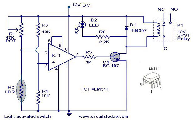
The following circuit illustrates a Light Activated Switch Circuit Diagram. This circuit is based on the LM311 integrated circuit, which functions as a voltage comparator. The Light Activated Switch Circuit utilizes the LM311 voltage comparator to control the switching of...
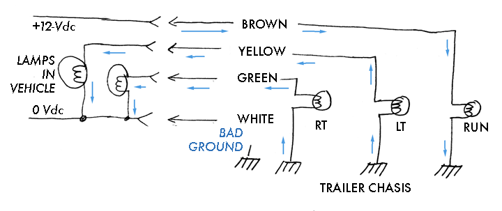
The boat trailer wiring was rewired due to damaged wiring and lights. A standard 4-pole flat connection is used to connect to the truck. The trailer features two rear lights and no side markers, with both rear lights grounded...
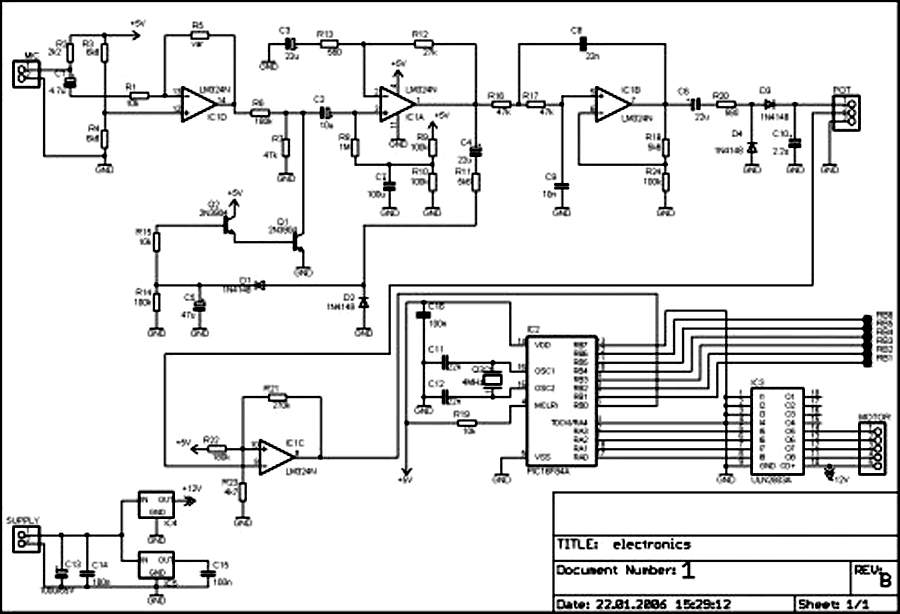
External circuit converts bass beat of music into pulses. The motor is controlled by them. If there's bass beat recognized then the motor rotates one direction (in full stepping) for a predefined time then stops. If the second beat...
The circuit operation principle of the device illustrated in Figure 11 addresses the frequent occurrence of power outages, particularly in critical situations where continuous power supply is essential, such as during surgeries. The circuit employs a simple design that...
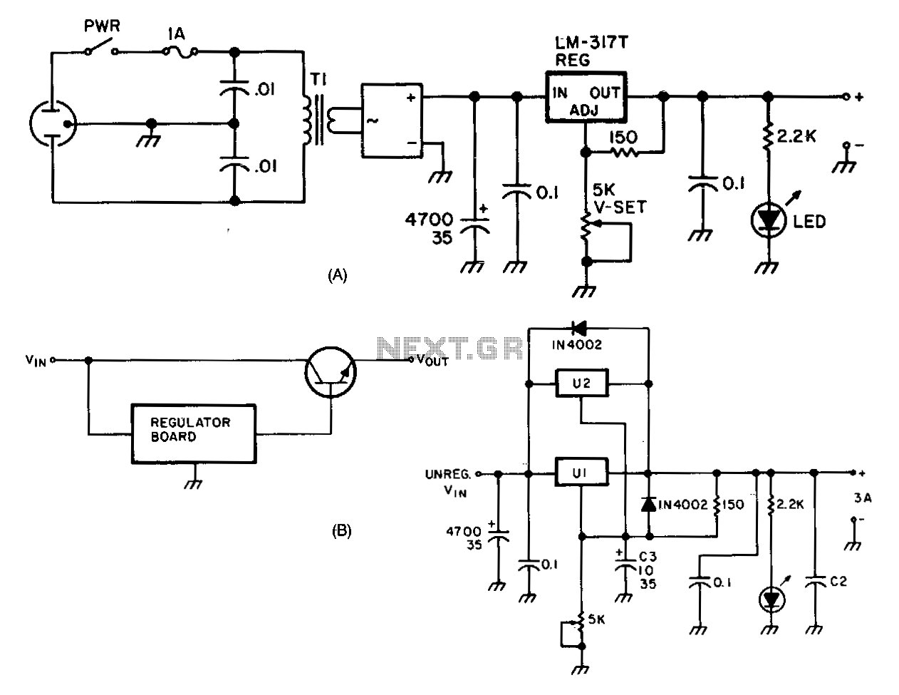
The LM317 adjustable regulator (U1) offers short-circuit protection and automatic current limiting at 1.5 A. The input voltage to the regulator is provided by a 4-A 100 PIV full-wave bridge rectifier (DB1). Capacitor C1 serves as the initial filtering...

This light-dependent sensor utilizes light-dependent resistors (LDRs) to detect the presence or absence of light. The alarm remains inactive as long as the light source illuminating the LDRs is constant. However, if the light is interrupted, the alarm is activated. The...