
Basic FET Amplifier
The FET amplifier circuit operates by utilizing field-effect transistors (FETs) to amplify signals. The FET's gate-source voltage (Vgs) is critical in controlling the conductivity of the channel between the source and drain. When the gate voltage is sufficiently negative compared to the source, it creates an electric field that depletes charge carriers in the channel, thus controlling the drain current (Id).
In the described configuration, the source resistor plays a pivotal role in establishing the biasing conditions. The voltage drop across the source resistor (Vs) is directly proportional to the drain current (Id), which is defined by Ohm's law (Vs = Id * Rs). This feedback mechanism ensures that as the drain current increases, the voltage drop across the source resistor increases, effectively lowering the gate-source voltage and stabilizing the operating point of the amplifier.
The relationship between the gate voltage and drain current elucidates the amplifier's operation: an increase in the input signal (applied to the gate) leads to an increase in drain current, which in turn modifies the drain voltage in an inverse manner. This characteristic enables the FET amplifier to function effectively in various applications, including audio processing.
The inclusion of the JFET switch using the MPF102 allows for versatile circuit configurations, as the symmetrical nature of the JFET permits flexibility in how the circuit can be implemented. The use of an audio mixer highlights the practical application of such circuits in real-world scenarios, where multiple audio signals are combined, maintaining signal integrity through simple addition.
In summary, the FET amplifier circuit demonstrates a fundamental approach to signal amplification, leveraging the unique properties of FETs and associated components to achieve desired electrical characteristics while ensuring stable operation across varying input conditions.This is The Fet Amplifier circuit. This circuit uses FET transistor. The gate of the FET must be negative with respect to the source, so a bias can be achieved in the following manner. The voltage that is across the source resistor is developed by the drain current flowing through the source resistor.
Due to that action, the emitter become positiv e with respect the zero volts rail. Here is the schematic diagram of the circuit: The fet is biased correctly, since the current does not flow at gate make the gate has a zero volts. So, the gate is negative with respect to the source because the source is positive with respect to the gate.
The drain current is controlled by the signal voltage that is applied to the gate. The drain current will be decreased when the signal goes less positive. It will make the drain voltage goes more positive because just a little voltage across the drain resistor. The drain voltage will goes more negative and more voltage across the drain resistor when the drain current is increased because the signal voltage goes more positive.
So, the drain voltage does the opposite of the gate voltage. The silicon controlled rectifier (S. C. R. ) is called as the thyristor. It is like a diode, when the cathode is negative with respect to the anode, the current flowing from cathode to anode. But, the difference of thyristor and diode is Continue reading †’. This is a JFET switch circuit. This circuit uses a MPF102 JFET transistor. In this circuit, the JFET is symmetrical, so the input can be source or drain. The MPF102 is used because this transistor has gate`s reverse breakdown voltage of Continue reading †’.
Audio mixer is used to mix several audio signal from many channel into one channel, in analog form. The basic requirement of an audio mixer is that the mixed signal is a product of simple addition. When connected to several Continue reading †’. Using a FET and two additional transistors (cascaded to improve the gain), a 5V FET voltage regulator can be formed. The additional Tr2 and Tr3 transistors will improve the output current handling and decrease the output impedance.
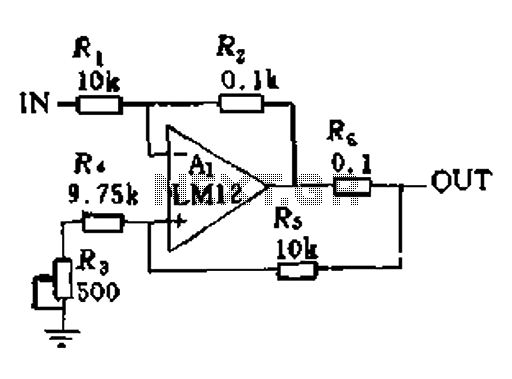
The output voltage Continue reading †’. Sometimes, in linear equipment design, it`s necessary to take a voltage which is referred to some dc level and generate an amplified output which is referred to ground. Using a differential amplifier similar to that shown in the circuit diagram Continue reading †’. 🔗 External reference
Related Circuits
This microphone preamplifier utilizes the low-noise integrated circuit (IC) uA739. It serves as a practical example of designing an effective preamplifier for dynamic microphones. The IC contains two identical integrated preamplifier circuits, with the second preamp functioning in the...
The LH0024 is a small signal integrated circuit (IC) designed for general-purpose switching and amplification due to its low voltage characteristics. Additionally, it utilizes three 1N4148 silicon small signal diodes, which are planar epitaxial devices used for fast switching...

This is a BTL (bridged tied load) mono amplifier with a DC volume control circuit. This circuit utilizes the TDA7052A/AT, which is suitable for monitors, TVs, and battery-operated portable radios and recorders. Unlike conventional DC volume circuits, the TDA7052A/AT...
The amplifier in question is comparable to another model that has a lower parts count. It is worthy of construction. The amplifier under discussion features a simplified design that maintains high performance while reducing the number of components required for...
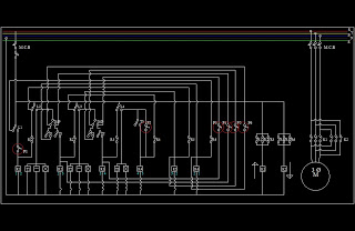
This is a basic lift circuit. When the P1 push button is pressed, the lift starts operating from the 1st floor to the 2nd floor. After a specified time duration, it automatically moves to the 3rd floor. The same...
In a servo system, the current drive connection is frequently utilized. The output current (IOUT) is proportional to the input channel number (y). Using the current drive mode can mitigate issues caused by the motor's large inductance, which induces...
Warning: include(partials/cookie-banner.php): Failed to open stream: Permission denied in /var/www/html/nextgr/view-circuit.php on line 713
Warning: include(): Failed opening 'partials/cookie-banner.php' for inclusion (include_path='.:/usr/share/php') in /var/www/html/nextgr/view-circuit.php on line 713