
Electro harmonix graphic equalizer circuit

The Electro-Harmonix graphic equalizer diagram serves as a versatile tool for audio signal processing, allowing users to customize the number of channels based on their specific needs. The core components include capacitors C1 and C2, resistor R1, an operational amplifier, a potentiometer for adjusting levels, and a 470-ohm resistor, all of which are arranged in parallel to achieve the desired frequency response. The selection of C1, C2, and R1 directly influences the frequencies that can be boosted, making it essential to refer to the schematic for precise values and configurations.
The Electro-Harmonix Soul Preacher pedal circuit diagram is designed with high-quality components. The use of carbon film resistors rated at 1/4W with a tolerance of 5% ensures reliable performance, while the mylar capacitors rated at 50V and 10% tolerance contribute to the overall stability of the circuit. The operational amplifier IC1, a 4558, is known for its low noise characteristics, making it suitable for audio applications. The schematic may also include details on the layout and connections for optimal performance.
In the fuzz-wah guitar effect pedal circuit, the incorporation of transistors Q1 and Q2, specifically the 2N3565, enhances the tonal characteristics of the effect. The true bypass feature provided by switch S1 allows for seamless transitions between effect and bypass modes, ensuring that the original signal remains unaltered when the effect is not in use. The pedal's design also includes several switches (S2 to S5) that allow users to toggle between fuzz, wah-wah, and volume settings, as well as adjust tone, providing a comprehensive range of sound manipulation options.
The EH Big Muff Pi pedal schematic highlights the potential for modern upgrades, such as the addition of a contemporary input jack power and a DPDT bypass switch, which can enhance usability and performance. The unspecified transistors and diodes indicate flexibility in component selection, suggesting that any high-gain NPN transistors could be utilized in the circuit without compromising functionality.
The Electro-Harmonix Small Stone Phaser circuit is notable for its unique use of Operational Transconductance Amplifiers (OTAs) in the phase shift stages. This design choice allows for more precise control over the phasing effect compared to traditional operational amplifiers with variable resistors. The integrated circuits marked as EH1048 offer a proprietary solution, although replacements like the CA3094 are available, providing compatibility and performance consistency in the circuit design.
Overall, these schematics represent a wealth of information for audio engineers and enthusiasts, offering insights into the design and operation of various Electro-Harmonix guitar effect pedals. Each circuit is crafted to deliver specific sonic characteristics, allowing for a broad range of creative possibilities in music production and performance.This is the diagram od electro-harmonix graphic equalizer. You can specify the number of channels according to your needs. You just need to parallel the components: C1, C2, R1, an om-amp, Potensiometer and a 470 ohm resistor. The frequency to be boost decided by C1, C2 and R1. See the diagram for the C1, C2. This is the circuit diagram of Electro -Harmonix Soul Preacher pedal. Notes: -All resistors are carbon film, 1/4W, 5%, unless otherwise noted -All non-polarized capacitors are mylar, 50V, 10%, unless otherwise noted -Transistors Q1-4 and FET J1 are unknown -IC1 is a 4558 Download Electro-Harmonix Soul Preacher pedal circuit diagram in PDF file: » Download Link This is the electro harmonix fuzz-wah guitar effect pedal circuit diagram. Circuit Notes: Q1 & Q2 are 2n3565 Fuzz bypass S1 has been improved to provide true bypass S3 chooses volume or wah-wah S5 provides for sweep reverse S2 gives just fuzz, just wah-wah / volume, or fuzz into wah-wah / volume S4 sets tone.
The following diagram is the schematic diagram of electric guitar effect: Electro Harmonix (EH) Big Muff Pi. The EH Big Muff Pi would probably be better making the change by a modern input-jack power and a DPDT bypass switch.
The types of transistors and diodes are unknown. It is likely that any high gain NPN. This is the schematic diagram of Electro-Harmonix Small Stone Phaser guitar effect pedal. The Small Stone is somewhat special in applying Operational Transconductance Amplifiers (OTA`s) for phase shift stages rather of opamps with variable resistors. All of the IC`s are house marked EH1048, but could be replaced with CA3094 that is a combination of an.
🔗 External reference
Related Circuits
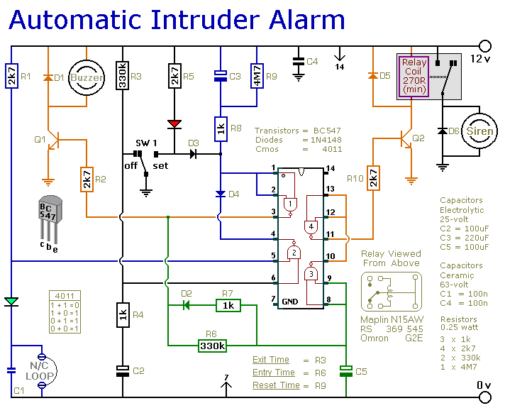
This is a simple single-zone burglar alarm circuit. Its features include automatic exit and entry delays and a timed bell/siren cut-off. It is designed to be used with the usual types of normally-closed input devices such as magnetic reed...
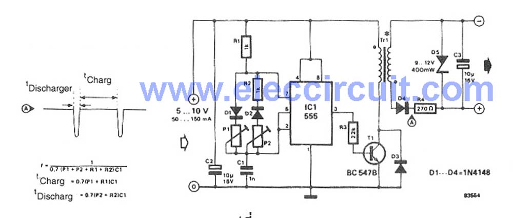
This circuit is a simple DC to DC converter designed for digital circuits. It operates with a supply voltage of 5V and provides an output voltage that steps up to a maximum of 10V-12V DC. The circuit utilizes an...
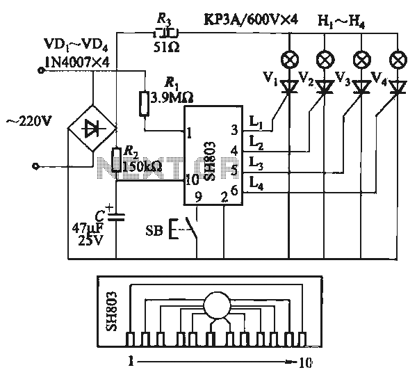
The circuit utilizes the SH803 flash IC, which can store eight different programs and offers various dimming options and light speed adjustments. A button is provided to trigger the control terminal SB on the 9-pin connector for program selection,...
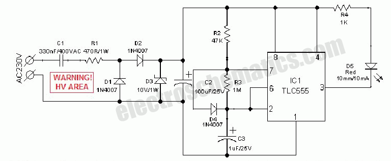
An AC mains operated single LED flasher circuit is constructed using the widely utilized CMOS timer chip TLC555. The entire circuit is powered directly from the 230VAC grid supply via a capacitive potential divider and associated components. This compact...
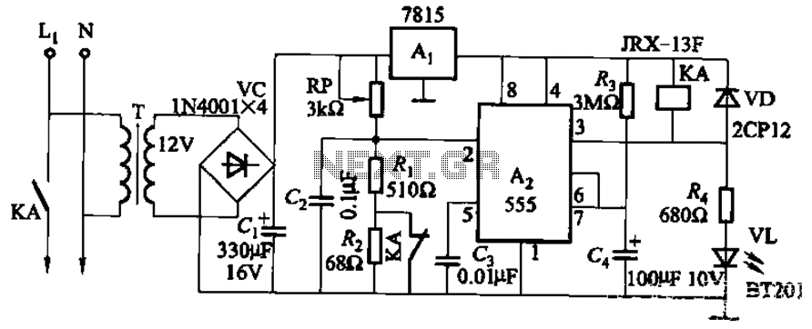
This circuit is applicable in refrigerators and other protective devices. It employs a 7815 three-terminal voltage regulator integrated circuit and an NE555 timer IC configured as a one-shot circuit for delay control. When the voltage drops below 180V, relay...
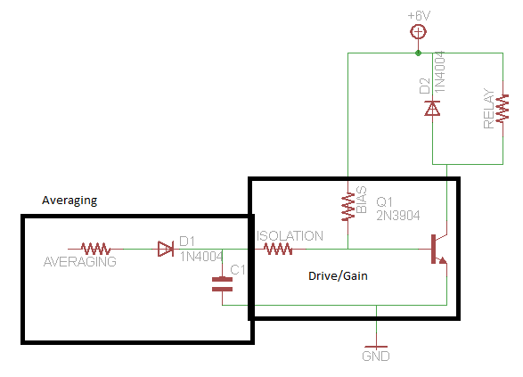
A circuit that activates a relay upon detecting audio pulses from one channel of an MP3 player. The intention is to synchronize recorded audio pulses with music to control a motor for mouth movement. For a stereo player, music...